HP 15-g029wm HP 15 Notebook PC Compaq 15 Notebook PC Maintenance and Service G - Page 42
back of the panel, On the back of the display panel, release the adhesive strip
 |
View all HP 15-g029wm manuals
Add to My Manuals
Save this manual to your list of manuals |
Page 42 highlights
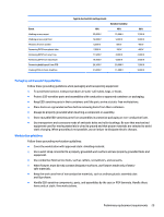
b. Rotate the display panel onto the keyboard to gain access to the display cable connection on the back of the panel (1). c. On the back of the display panel, release the adhesive strip (2) that secures the display panel cable to the display panel, and then disconnect the cable (3). Reverse this procedure to reassemble and install the display bezel, webcam/microphone module, and display panel. 34 Chapter 4 Removal and replacement procedures
-
 1
1 -
2
-
3
-
4
-
5
-
6
-
7
-
8
-
9
-
10
-
11
-
12
-
13
-
14
-
15
-
16
-
17
-
18
-
19
-
20
-
21
-
22
-
23
-
24
-
25
-
26
-
27
-
28
-
29
-
30
-
31
-
32
-
33
-
34
-
35
-
36
-
 37
37 -
 38
38 -
 39
39 -
 40
40 -
 41
41 -
 42
42 -
 43
43 -
 44
44 -
 45
45 -
 46
46 -
 47
47 -
48
-
49
-
50
-
51
-
52
-
53
-
54
-
55
-
56
-
57
-
58
-
59
-
60
-
61
-
62
-
63
-
64
-
65
-
66
-
67
-
68
-
69
-
70
-
71
-
72
-
73
-
74
-
75
-
76
-
77
-
78
-
79
-
80
-
81
-
82
-
83
-
84
-
85
-
86
-
87
-
88
-
89
-
90
-
91
-
92
-
93
-
94
-
95
-
96
-
97
-
98
-
99
-
100
-
101
-
102
-
103
-
104
-
105
-
106
-
107
-
108
-
109
-
110
-
111
-
112
-
113
-
114
-
115
-
116
-
117
-
118
 |
 |

b.
Rotate the display panel onto the keyboard to gain access to the display cable connection on the
back of the panel
(1)
.
c.
On the back of the display panel, release the adhesive strip
(2)
that secures the display panel cable
to the display panel, and then disconnect the cable
(3)
.
Reverse this procedure to reassemble and install the display bezel, webcam/microphone module, and display
panel.
34
Chapter 4
Removal and replacement procedures