HP 15-r200 15 Notebook PC 15 TouchSmart Notebook PC 15 Notebook PC 15 TouchSma - Page 59
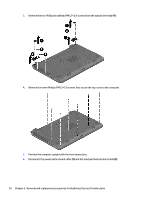
Remove the four Phillips PM2.5×3.5 screws that secure the display panel to the enclosure.
 |
View all HP 15-r200 manuals
Add to My Manuals
Save this manual to your list of manuals |
Page 59 highlights
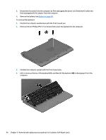
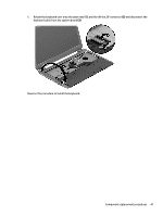
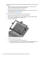
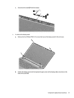
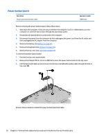
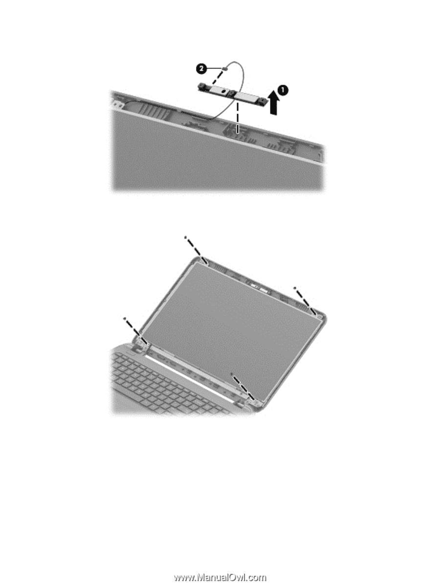
c. Disconnect the cable (2) from the module. 5. To remove the display panel: a. Remove the four Phillips PM2.5×3.5 screws that secure the display panel to the enclosure. b. Rotate the display panel onto the keyboard to gain access to the display cable connection on the back of the panel (1). Component replacement procedures 51
-
 1
1 -
2
-
3
-
4
-
5
-
6
-
7
-
8
-
9
-
10
-
11
-
12
-
13
-
14
-
15
-
16
-
17
-
18
-
19
-
20
-
21
-
22
-
23
-
24
-
25
-
26
-
27
-
28
-
29
-
30
-
31
-
32
-
33
-
34
-
35
-
36
-
37
-
38
-
39
-
40
-
41
-
42
-
43
-
44
-
45
-
46
-
47
-
48
-
49
-
50
-
51
-
52
-
53
-
 54
54 -
 55
55 -
 56
56 -
 57
57 -
 58
58 -
 59
59 -
 60
60 -
 61
61 -
 62
62 -
 63
63 -
 64
64 -
65
-
66
-
67
-
68
-
69
-
70
-
71
-
72
-
73
-
74
-
75
-
76
-
77
-
78
-
79
-
80
-
81
-
82
-
83
-
84
-
85
-
86
-
87
-
88
-
89
-
90
-
91
-
92
-
93
-
94
-
95
-
96
-
97
-
98
-
99
-
100
-
101
-
102
-
103
-
104
-
105
-
106
-
107
-
108
-
109
-
110
-
111
-
112
-
113
-
114
-
115
-
116
-
117
-
118
-
119
-
120
-
121
-
122
-
123
-
124
 |
 |
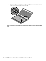
c.
Disconnect the cable
(2)
from the module.
5.
To remove the display panel:
a.
Remove the four Phillips PM2.5×3.5 screws that secure the display panel to the enclosure.
b.
Rotate the display panel onto the keyboard to gain access to the display cable connection on the
back of the panel
(1)
.
Component replacement procedures
51