HP 15-r200 15 Notebook PC 15 TouchSmart Notebook PC 15 Notebook PC 15 TouchSma - Page 80
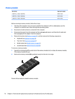
Heat sink assembly, Reverse this procedure to install the speakers.
 |
View all HP 15-r200 manuals
Add to My Manuals
Save this manual to your list of manuals |
Page 80 highlights
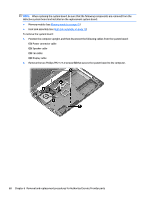
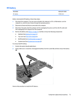
Reverse this procedure to install the speakers. Heat sink assembly NOTE: The heat sink assembly spare part kit includes replacement thermal materials. Description Spare part number Heat sink for use in models with UMA graphics and the following Intel processors: i7-4510U, i5-4210U, i3-4005U 759880-001 Heat sink for use in models with discrete graphics and the following Intel processors: i7-4510U, i5-4210U, i3-4005U 759881-001 Heat sink for use in models with Intel Pentium or Celeron processors and UMA graphics 767537-001 Heat sink for use in models with Intel i3-3217U processors and discrete graphics 767538-001 Heat sink for use in models with Intel i3-3217U processors and UMA graphics 767539-001 NOTE: To properly ventilate the computer, allow at least 7.6 cm (3.0 in) of clearance on the left side of the computer. The computer uses an electric fan for ventilation. The fan is controlled by a temperature sensor and is designed to turn on automatically when high temperature conditions exist. These conditions are affected by high external temperatures, system power consumption, power management/battery conservation configurations, battery fast charging, and software requirements. Exhaust air is displaced through the ventilation grill located on the left side of the computer. Before removing the heat sink assembly, follow these steps: 1. Shut down the computer. If you are unsure whether the computer is off or in Hibernation, turn the computer on, and then shut it down through the operating system. 2. Disconnect all external devices connected to the computer. 3. Disconnect the power from the computer by first unplugging the power cord from the AC outlet and then unplugging the AC adapter from the computer. 4. Remove the battery (see Battery on page 41), and then remove the following components: ● Keyboard (see Keyboard on page 45) ● Top cover (see Top cover on page 53) ● WLAN module (see WLAN module on page 61) ● System board (see System board on page 66) To remove the heat sink assembly: 1. Position the system board upside down. 2. Loosen the screws on the heat sink (1) that secure the heat sink assembly to the system board. 72 Chapter 6 Removal and replacement procedures for Authorized Service Provider parts
-
 1
1 -
2
-
3
-
4
-
5
-
6
-
7
-
8
-
9
-
10
-
11
-
12
-
13
-
14
-
15
-
16
-
17
-
18
-
19
-
20
-
21
-
22
-
23
-
24
-
25
-
26
-
27
-
28
-
29
-
30
-
31
-
32
-
33
-
34
-
35
-
36
-
37
-
38
-
39
-
40
-
41
-
42
-
43
-
44
-
45
-
46
-
47
-
48
-
49
-
50
-
51
-
52
-
53
-
54
-
55
-
56
-
57
-
58
-
59
-
60
-
61
-
62
-
63
-
64
-
65
-
66
-
67
-
68
-
69
-
70
-
71
-
72
-
73
-
74
-
 75
75 -
 76
76 -
 77
77 -
 78
78 -
 79
79 -
 80
80 -
 81
81 -
 82
82 -
 83
83 -
 84
84 -
 85
85 -
86
-
87
-
88
-
89
-
90
-
91
-
92
-
93
-
94
-
95
-
96
-
97
-
98
-
99
-
100
-
101
-
102
-
103
-
104
-
105
-
106
-
107
-
108
-
109
-
110
-
111
-
112
-
113
-
114
-
115
-
116
-
117
-
118
-
119
-
120
-
121
-
122
-
123
-
124
 |
 |