HP 2000-2b30DX HP 2000 Notebook PC Compaq Presario CQ58 Notebook PC Compaq Pre - Page 50
Remove the Phillips PM2.0×3.0 screw, WLAN antenna cable is connected to the WLAN module Aux terminal.
 |
View all HP 2000-2b30DX manuals
Add to My Manuals
Save this manual to your list of manuals |
Page 50 highlights
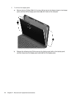
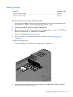
To remove the WLAN module: 1. Loosen the memory module/wireless module compartment cover screw (1), and then lift up on the tab (2) and remove the cover (3). The memory module/wireless module compartment cover is available in the Plastics Kit. For more information about the Plastics Kit, see Plastics kit on page 22. 2. Disconnect the WLAN antenna cables (1) from the terminals on the WLAN module. NOTE: The #1 WLAN antenna cable is connected to the WLAN module Main terminal. The #2 WLAN antenna cable is connected to the WLAN module Aux terminal. 3. Remove the Phillips PM2.0×3.0 screw (2) that secures the WLAN module to the system board. (The WLAN module tilts up.) Component replacement procedures 43
-
 1
1 -
2
-
3
-
4
-
5
-
6
-
7
-
8
-
9
-
10
-
11
-
12
-
13
-
14
-
15
-
16
-
17
-
18
-
19
-
20
-
21
-
22
-
23
-
24
-
25
-
26
-
27
-
28
-
29
-
30
-
31
-
32
-
33
-
34
-
35
-
36
-
37
-
38
-
39
-
40
-
41
-
42
-
43
-
44
-
 45
45 -
 46
46 -
 47
47 -
 48
48 -
 49
49 -
 50
50 -
 51
51 -
 52
52 -
 53
53 -
 54
54 -
 55
55 -
56
-
57
-
58
-
59
-
60
-
61
-
62
-
63
-
64
-
65
-
66
-
67
-
68
-
69
-
70
-
71
-
72
-
73
-
74
-
75
-
76
-
77
-
78
-
79
-
80
-
81
-
82
-
83
-
84
-
85
-
86
-
87
-
88
-
89
-
90
-
91
-
92
-
93
-
94
-
95
-
96
-
97
-
98
-
99
-
100
-
101
-
102
-
103
-
104
-
105
-
106
-
107
-
108
-
109
-
110
-
111
-
112
-
113
-
114
-
115
-
116
-
117
-
118
-
119
-
120
-
121
-
122
-
123
-
124
-
125
-
126
-
127
-
128
-
129
 |
 |

To remove the WLAN module:
1.
Loosen the memory module/wireless module compartment cover screw
(1)
, and then lift up on
the tab
(2)
and remove the cover
(3)
. The memory module/wireless module compartment cover
is available in the Plastics Kit. For more information about the Plastics Kit, see
Plastics kit
on page
22
.
2.
Disconnect the WLAN antenna cables
(1)
from the terminals on the WLAN module.
NOTE:
The #1 WLAN antenna cable is connected to the WLAN module Main terminal. The #2
WLAN antenna cable is connected to the WLAN module Aux terminal.
3.
Remove the Phillips PM2.0×3.0 screw
(2)
that secures the WLAN module to the system board.
(The WLAN module tilts up.)
Component replacement procedures
43