HP 2x1Ex16 HP IP and Server Console Switches G2 User Guide - Page 10
Description, 2x1Ex16 or 4x1Ex32, Power connectors A & B
 |
View all HP 2x1Ex16 manuals
Add to My Manuals
Save this manual to your list of manuals |
Page 10 highlights
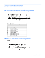
Item 1 2 3 4 5 6 7 8 9 10 11 Description Power supply status indicator LEDs LAN 1 LAN 2 S1, S2, and S3 (reserved for future use) Tiering chain port RJ-45 serial setup port Local console VGA Local console USB ports Interface adapter ports (1-4) Interface adapter ports (5-8) Power connectors A & B 2x1Ex16 or 4x1Ex32 Item 1 2 3 4 5 6 7 8 9 10 Description Power supply status indicator LEDs LAN 1 and LAN 2 S1, S2, and S3 (reserved for future use) Tiering chain port RJ-45 serial setup port Local console VGA Local console USB ports Interface adapter ports (1-16) Interface adapter ports (17-32) Power connectors A & B Component identification 10
-
 1
1 -
2
-
3
-
4
-
 5
5 -
 6
6 -
 7
7 -
 8
8 -
 9
9 -
 10
10 -
 11
11 -
 12
12 -
 13
13 -
 14
14 -
 15
15 -
16
-
17
-
18
-
19
-
20
-
21
-
22
-
23
-
24
-
25
-
26
-
27
-
28
-
29
-
30
-
31
-
32
-
33
-
34
-
35
-
36
-
37
-
38
-
39
-
40
-
41
-
42
-
43
-
44
-
45
-
46
-
47
-
48
-
49
-
50
-
51
-
52
-
53
-
54
-
55
-
56
-
57
-
58
-
59
-
60
-
61
-
62
-
63
-
64
-
65
-
66
-
67
-
68
-
69
-
70
-
71
-
72
-
73
-
74
-
75
-
76
-
77
-
78
-
79
-
80
-
81
-
82
-
83
 |
 |

Component identification 10
Item
Description
1
Power supply status indicator LEDs
2
LAN 1
3
LAN 2
4
S1, S2, and S3 (reserved for future use)
5
Tiering chain port
6
RJ-45 serial setup port
7
Local console VGA
8
Local console USB ports
9
Interface adapter ports (1-4)
10
Interface adapter ports (5-8)
11
Power connectors A & B
2x1Ex16 or 4x1Ex32
Item
Description
1
Power supply status indicator LEDs
2
LAN 1 and LAN 2
3
S1, S2, and S3 (reserved for future use)
4
Tiering chain port
5
RJ-45 serial setup port
6
Local console VGA
7
Local console USB ports
8
Interface adapter ports (1-16)
9
Interface adapter ports (17-32)
10
Power connectors A & B