HP 2x1Ex16 HP IP and Server Console Switches G2 User Guide - Page 15
Required items not included, Required tools, Rack-mounting the console switch
 |
View all HP 2x1Ex16 manuals
Add to My Manuals
Save this manual to your list of manuals |
Page 15 highlights
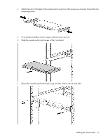
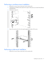
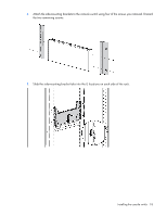
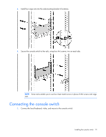
Required items not included • Interface adapters ("Installing the interface adapter" on page 23) One interface adapter is needed for each server or device. o USB o PS2 o Serial o HP BladeSystem • UTP CAT 5 or better cable • Cage nuts and M6 screws (included with your original rack hardware kit) Required tools The following tools are required for some procedures: • Phillips screwdriver • Cage nut insertion tool (included with your original rack hardware kit) Rack-mounting the console switch WARNING: For safe use, do not mount this product with the rear panel, which is the side of the console switch with I/O connectors and the AC power inlet, facing downward (facing the floor). 1. Before installing the console switch into the rack, connect the console switch to a power source using the power cords provided. An activity indicator light is displayed after a few seconds. If the activity indicator light does not display, be sure that the power cord is connected, and the power source is valid. 2. Choose one of the following configurations: o Standard-mount o Cantilever-mount o Side-mount Performing a standard-mount installation 1. Remove the six screws, three on each side, from the console switch. Installing the console switch 15
-
 1
1 -
2
-
3
-
4
-
5
-
6
-
7
-
8
-
9
-
 10
10 -
 11
11 -
 12
12 -
 13
13 -
 14
14 -
 15
15 -
 16
16 -
 17
17 -
 18
18 -
 19
19 -
 20
20 -
21
-
22
-
23
-
24
-
25
-
26
-
27
-
28
-
29
-
30
-
31
-
32
-
33
-
34
-
35
-
36
-
37
-
38
-
39
-
40
-
41
-
42
-
43
-
44
-
45
-
46
-
47
-
48
-
49
-
50
-
51
-
52
-
53
-
54
-
55
-
56
-
57
-
58
-
59
-
60
-
61
-
62
-
63
-
64
-
65
-
66
-
67
-
68
-
69
-
70
-
71
-
72
-
73
-
74
-
75
-
76
-
77
-
78
-
79
-
80
-
81
-
82
-
83
 |
 |
