HP 6125XLG R2306-HP 6125XLG Blade Switch TRILL Configuration Guide - Page 16
TRILL configuration example, Network requirements, Configuration procedure
 |
View all HP 6125XLG manuals
Add to My Manuals
Save this manual to your list of manuals |
Page 16 highlights
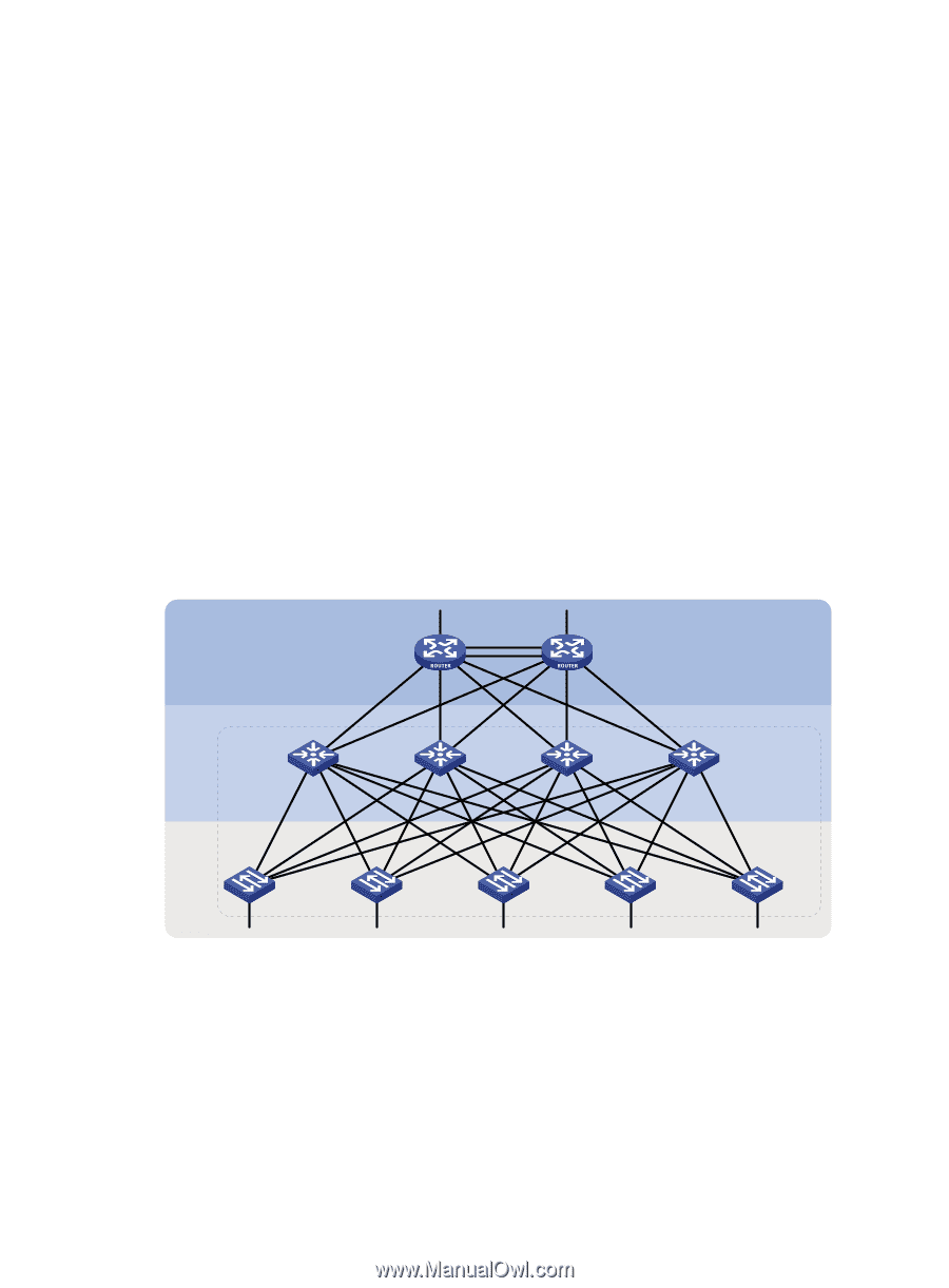
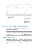
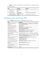
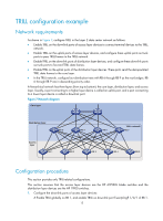
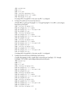
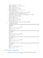
TRILL configuration example Network requirements As shown in Figure 7, configure TRILL in the Layer 2 data center network as follows: • Enable TRILL on the downlink ports of access layer devices to connect terminal devices to the TRILL network. • Enable TRILL on the uplink ports of access layer devices, and configure these uplink ports as trunk ports to pass TRILL frames to the TRILL network. • Enable TRILL on the downlink ports of distribution layer devices, and configure these downlink ports as trunk ports to forward TRILL data frames. • Enable TRILL on the uplink ports of the distribution layer devices. These ports send the decapsulated TRILL data frames to the core layer. • In the TRILL network, configure four distribution trees with RB 6 through RB 9 as the root bridges. RB 6 through RB 9 are in descending priority order. A hierarchical network has three layers (from top to bottom): the core layer, distribution layer, and access layer. Usually, a port connecting to a higher layer device is called an uplink port, and a port connecting to a lower layer device is called a downlink port. Figure 7 Network diagram Core layer Distribution layer RB 6 RB 7 RB 8 TRILL network RB 9 Access layer RB 1 RB 2 RB 3 RB 4 RB 5 Configuration procedure This section provides only TRILL-related configurations. This section assumes that the access layer devices are the HP 6125XLG blade switches and the distribution layer devices are the HP 11900 switches. 1. Configure the downlink ports of access layer devices: # Enable TRILL globally on RB 1, and enable TRILL on downlink port TwentyGigE 1/0/1 of RB 1. 13
-
 1
1 -
2
-
3
-
4
-
5
-
6
-
7
-
8
-
9
-
10
-
 11
11 -
 12
12 -
 13
13 -
 14
14 -
 15
15 -
 16
16 -
 17
17 -
 18
18 -
 19
19 -
 20
20 -
 21
21 -
22
-
23
-
24
-
25
 |
 |