HP Brocade 8/12c DATA CENTER Best Practices Guide: High Density Cable Manageme - Page 11
Setup and Configuration - Up to 256 Port Solution, the Commercial Telecommunications Infrastructure.
 |
View all HP Brocade 8/12c manuals
Add to My Manuals
Save this manual to your list of manuals |
Page 11 highlights
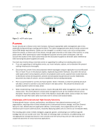
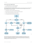
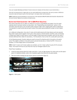
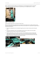
DATA CENTER BEST PRACTICES GUIDE (You can exclude Building and Room if there is only one instance of this entity in your environment.) Once the naming scheme is approved, you can start labeling the components. Be sure to create a reference document that will become part of the training for new data center administrators. NOTE: Additional recommendations can be found in the standard ANSI/TIA-606 Administration Standard for the Commercial Telecommunications Infrastructure. SETUP AND CONFIGURATION - UP TO 256 PORT SOLUTION This section describes how to cable up a 256 port LC solution using FC8-64 port blades. Once the cable labeling scheme has been defined, as described in the "Establishing a Naming Scheme" section in this document, label the ports on the LC patch panel using the cable to port mapping table listed in Appendix A. It is important to map the DCX slot and port number to the patch panel/shelf/port number on the LC patch panel. For a 256 port configuration, four sets of 1 rack unit LC patch panels with three shelves each are required. Each 1RU LC patch panel supports 72 LC ports, which maps to a director blade. Therefore, when connecting a FC8-64 port blade to a patch panel, it will have eight LC patch panel ports available, which can be used to allocate additional fiber cables for redundancy. For this solution, there will be 32 unused patch panel ports. In the following example, 2-meter cables are used to connect the director ports to the ports on the patch panel. This length is sufficient if the patch panel is placed directly above or below the DCX. If this is not possible, a 3-meter length cable is recommended. NOTE: If both 1-meter and 2-meter cables are available, use the 2-meter cables for ports 16-31 and ports 48-63. This would minimize the extra fiber that must be managed inside the rack. Patch Panel Installation: 1. Install the patch panels below the cable comb with a 1 rack unit gap between the cable comb and the patch panel. For additional details, refer to the installation guide that ships with the patch panels. 2. Test each shelf by sliding out each tray for service accessibility (Figure 5). Figure 5. Patch panel Brocade DCX Cable Management 11 of 23
-
 1
1 -
2
-
3
-
4
-
5
-
 6
6 -
 7
7 -
 8
8 -
 9
9 -
 10
10 -
 11
11 -
 12
12 -
 13
13 -
 14
14 -
 15
15 -
 16
16 -
17
-
18
-
19
-
20
-
21
-
22
-
23
 |
 |