HP Brocade 8/12c DATA CENTER Best Practices Guide: High Density Cable Manageme - Page 15
Caution,
 |
View all HP Brocade 8/12c manuals
Add to My Manuals
Save this manual to your list of manuals |
Page 15 highlights
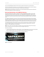
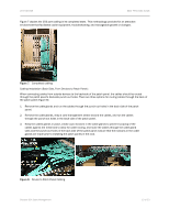
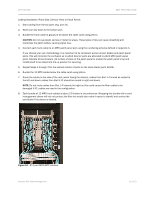
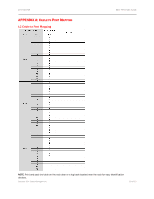
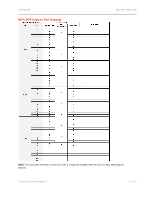
DATA CENTER BEST PRACTICES GUIDE Cabling Installation (Front Side, Director Ports to Patch Panel): 1. Start cabling from the top ports (e.g. port 31). 2. Work your way down to the bottom port. 3. Bundle the trunk cable in groups of six above the cable comb using Velcro. CAUTION: Do not use plastic zip ties or metal tie wraps. These types of ties can cause sheathing and overstress the patch cables, causing signal loss. 4. Connect each trunk cable to an MPO patch panel port using the numbering schema defined in Appendix A. If you choose your own methodology, it is important to be consistent across all port blades and patch panel ports. This will minimize the confusion as to which director ports are allocated to which MPO patch panel ports. Allocate 30-centimeters (12-inches) of slack at the patch panel to enable the patch panel's top and middle shelf to be raised into the up position for servicing. 5. Repeat Steps 1 through 4 for the second column of ports on the same blade (ports 32-63). 6. Bundle the 12 MPO cables below the cable comb using Velcro. 7. Route the cables to the side of the rack (when facing the director, cables from Slot 1-4 should be routed to the left and down; cables from Slot 9-12 should be routed to right and down). NOTE: Do not route cables from Slot 1-4 towards the right as this could cause the fiber cables to be damaged if ICL cables are used in the configuration. 8. Each bundle of 12 MPO trunk cables is about 2.5-inches in circumference. Wrapping this bundle with a cord management sleeve will not only protect the fiber but would also make it easier to identify and service the port blade if the sleeve is labeled. Figure 10. 512 port MPO/MTP solution Brocade DCX Cable Management 15 of 23
-
 1
1 -
2
-
3
-
4
-
5
-
6
-
7
-
8
-
9
-
 10
10 -
 11
11 -
 12
12 -
 13
13 -
 14
14 -
 15
15 -
 16
16 -
 17
17 -
 18
18 -
 19
19 -
 20
20 -
21
-
22
-
23
 |
 |