HP Dc7900 Hardware Reference Guide - dc7900 Series Convertible Minitower - Page 40
Installing a 5.25-inch or 3.5-inch Drive into an External Drive Bay, CAUTION,
 |
UPC - 884962028483
View all HP Dc7900 manuals
Add to My Manuals
Save this manual to your list of manuals |
Page 40 highlights
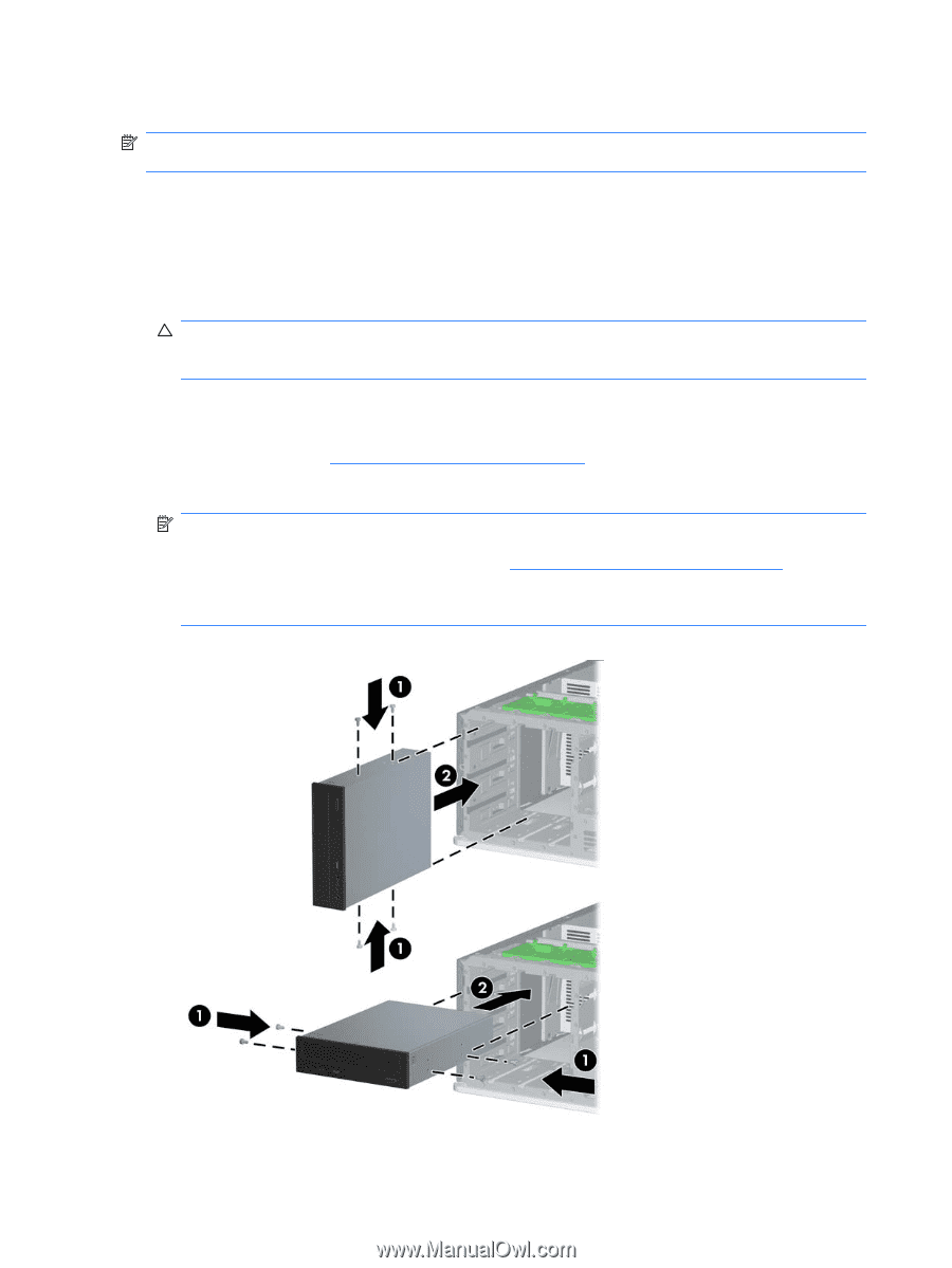
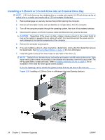
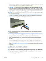
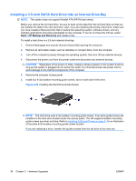
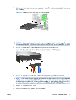
Installing a 5.25-inch or 3.5-inch Drive into an External Drive Bay NOTE: A 3.5-inch drive may be a diskette drive or a media card reader. A 5.25-inch drive may be an optical drive or a media card reader with a 5.25-inch adapter kit attached. 1. Remove/disengage any security devices that prohibit opening the computer. 2. Remove all removable media, such as diskettes or compact discs, from the computer. 3. Turn off the computer properly through the operating system, then turn off any external devices. 4. Disconnect the power cord from the power outlet and disconnect any external devices. CAUTION: Regardless of the power-on state, voltage is always present on the system board as long as the system is plugged into an active AC outlet. You must disconnect the power cord to avoid damage to the internal components of the computer. 5. Remove the computer access panel. 6. If you are installing a drive in a bay covered by a bezel blank, remove the front bezel then remove the bezel blank. See Removing Bezel Blanks on page 15 for more information. 7. Install two guide screws in the lower holes on each side of the drive (1). NOTE: Optical drives, diskette drives, and media card readers use M3 metric guide screws. Eight extra metric guide screws are provided on the diskette drive bracket under the access panel. The HP-supplied metric screws are black. Refer to Installing Additional Drives on page 31 for an illustration of the extra M3 metric guide screws location. If you are replacing a drive, transfer the guides screws from the old drive to the new one. Figure 2-26 Installing a 5.25-Inch Drive in a Minitower (top) and Desktop (bottom) 34 Chapter 2 Hardware Upgrades ENWW
-
 1
1 -
2
-
3
-
4
-
5
-
6
-
7
-
8
-
9
-
10
-
11
-
12
-
13
-
14
-
15
-
16
-
17
-
18
-
19
-
20
-
21
-
22
-
23
-
24
-
25
-
26
-
27
-
28
-
29
-
30
-
31
-
32
-
33
-
34
-
 35
35 -
 36
36 -
 37
37 -
 38
38 -
 39
39 -
 40
40 -
 41
41 -
 42
42 -
 43
43 -
 44
44 -
 45
45 -
46
-
47
-
48
-
49
-
50
-
51
-
52
-
53
-
54
-
55
-
56
-
57
-
58
-
59
-
60
-
61
-
62
-
63
-
64
-
65
-
66
-
67
 |
 |