HP Dc7900 Hardware Reference Guide - dc7900 Series Convertible Minitower - Page 41
CAUTION, Connecting the Drive Cables Optical Drive shown
 |
UPC - 884962028483
View all HP Dc7900 manuals
Add to My Manuals
Save this manual to your list of manuals |
Page 41 highlights
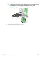
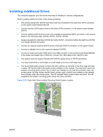
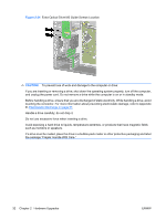
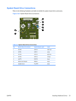
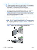
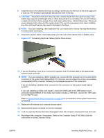
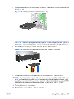
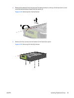
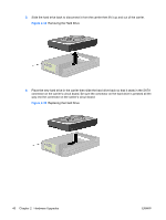
8. Install the drive in the desired drive bay by sliding it all the way into the front of the drive cage until it locks (2). The drivelock automatically secures the drive in the bay. CAUTION: The bottom 5.25-inch drive bay has a shorter depth than the upper two bays. The bottom bay supports a half-height drive or other device that is no more than 14.5 cm (5.7 inches) in depth. Do not try to force a larger drive, such as an optical drive, into the bottom bay. This could cause damage to the drive and the system board. The use of unnecessary force when installing any drive into the drive bay may result in damage to the drive. NOTE: If you are installing a third optional drive, you may need to remove the strap that bundles the extra power connectors. 9. Connect the power cable (1) and data cable (2) to the rear of the optical drive or diskette drive. Figure 2-27 Connecting the Drive Cables (Optical Drive shown) 10. If you are installing a new drive, connect the opposite end of the data cable to the appropriate system board connector. NOTE: If you are installing a SATA optical drive, connect the first optical drive to the white SATA connector on the system board labeled SATA1. Connect a second optical drive to the next available (unpopulated) SATA connector following the numbered sequence of the connectors. If you are installing a diskette drive, connect it to the connector on the system board labeled FLOPPY. If your are installing a media card reader, connect the USB cable to the USB system board connector labeled MEDIA. If the media card reader includes a 1394 port, connect the 1394 cable to the 1394 PCI card. Refer to System Board Drive Connections on page 33 for an illustration of the system board drive connectors. 11. Replace the front bezel and computer access panel. 12. Reconnect the power cord and turn on the computer. 13. Lock any security devices that were disengaged when the computer access panel was removed. 14. Reconfigure the computer, if necessary. Refer to the Computer Setup (F10) Utility Guide for instructions on using Computer Setup. ENWW Installing Additional Drives 35
-
 1
1 -
2
-
3
-
4
-
5
-
6
-
7
-
8
-
9
-
10
-
11
-
12
-
13
-
14
-
15
-
16
-
17
-
18
-
19
-
20
-
21
-
22
-
23
-
24
-
25
-
26
-
27
-
28
-
29
-
30
-
31
-
32
-
33
-
34
-
35
-
 36
36 -
 37
37 -
 38
38 -
 39
39 -
 40
40 -
 41
41 -
 42
42 -
 43
43 -
 44
44 -
 45
45 -
 46
46 -
47
-
48
-
49
-
50
-
51
-
52
-
53
-
54
-
55
-
56
-
57
-
58
-
59
-
60
-
61
-
62
-
63
-
64
-
65
-
66
-
67
 |
 |
