HP Designjet 4200 HP Designjet 4200 Scanner - Assembly and Maintenance Poster - Page 1
HP Designjet 4200 Manual
 |
View all HP Designjet 4200 manuals
Add to My Manuals
Save this manual to your list of manuals |
Page 1 highlights
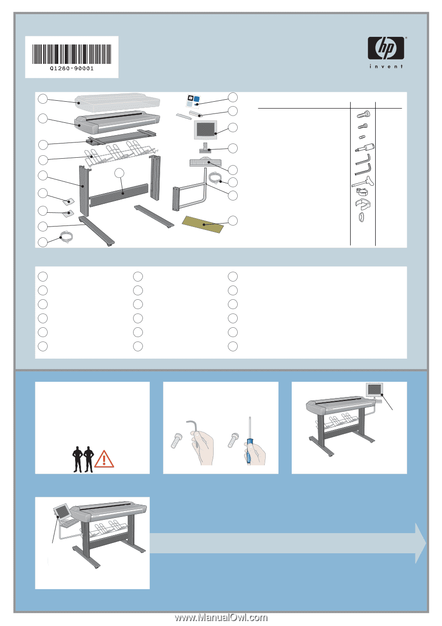
assembly instructions and routine maintenance procedures hp designjet scanner 4200 1 2 hp designjet copier cc800ps 3 4 5 10 6 7 8 9 systecmd-rroemcovery hp decsci8g0n0jept scopier 18 assembly kit contents description 17 screw M5×14 (Torx T25) for stand assembly 16 screw M4×8 for keyboard table and touch screen screw M3×8 for touch screen bracket 15 special screw for scanner Allen key 2.0mm for keyboard table and touch screen 14 Allen key 2.5mm for touch screen bracket 13 Torx 25 key 12 power cable clips wire routing clips plastic caps 11 quantity 20 5 1 4 1 1 1 12 5 4 1 plastic dust cover 2 scanner 3 top bar 4 basket 5 leg (×2) 6 maintenance kit 7 assembly kit 8 feet (×2) 9 power cables 10 lower bar 11 scanner maintenance sheet 12 touch screen arm 13 FireWire cable 14 keyboard table 15 touch screen bracket 16 touch screen 17 media guides (×2) 18 system recovery CD-ROM read these instructions carefully... and complete each stage before you start the next. what you will need to do the job Because some of the components of the scanner are bulky, you will need 2 or 3 people to lift them. See the descriptions that follow for details, a symbol like this is used: a note about fixings When initially assembling the scanner stand do not fully tighten the screws; you will be asked to do this later. touch screen assembly please note The touch screen assembly can be mounted on either the right or the left side of the stand. touch screen assembly please note The touch screen assembly can be mounted on either the right or the left side of the stand. 1
-
 1
1 -
 2
2 -
 3
3 -
 4
4 -
 5
5 -
 6
6
 |
 |