HP Designjet 4200 HP Designjet 4200 Scanner - Assembly and Maintenance Poster - Page 6
keep these instructions - software
 |
View all HP Designjet 4200 manuals
Add to My Manuals
Save this manual to your list of manuals |
Page 6 highlights
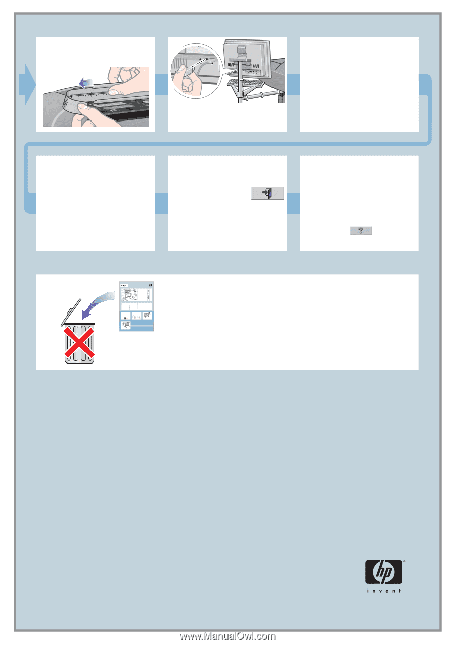
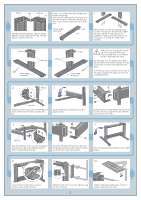
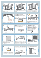
The scanner's ruler can be changed between centimeters and inches by sliding it out, turning it over, and reinserting it. 98 0 97 96 95 94 93 92 93 92 91 90 89 88 87 86 85 84 83 L A MmmR 2 O 4 N Inches 6 8 10D12TE1I4X1D6EN E T X E Inches0D.080.E160.D24T0. I3N10.X3E90E.47T0.550X.63E 40 Inches L AMRON To connect your scanner to a network, first connect the network cable to the Ethernet socket at the back of your touch screen as shown. Next, you should check the TCP/IP settings in your touch screen, and correct them if necessary. If you intend to scan to the network, you will also need to create a workgroup. You may want to share the Images folder in your touch screen so that it can be accessed from elsewhere on the network. For more guidance on these steps, see the online help system. When System Administrators configure your system in a network domain, they will also need to set up automatic login. This procedure is documented in "how do I set up automatic login" in your online help. To add an HP Designjet printer to the printer list in your scanner software, follow these steps: 1. On the touch screen, press the Quit button and then the Exit button to exit the scanner software. 2. Press the System Setup button. 3. Press the Install HP Designjet button. 4. Follow the instructions on the screen. For any further information on how to use your scanner, see the online help system available from your touch screen using the button below. assembly instructions and routine maintenance procedures hp designjet scanner 4200 1 2 hp designjet copier cc800ps 3 4 5 10 6 7 8 9 system recovery hp designjet copier cc800ps cd-rom 18 assembly kit contents description 17 screw M5×14 (Torx T25) for stand assembly 16 screw M4×8 for keyboard table and touch screen screw M3×8 for touch screen bracket 15 special screw for scanner Allen key 2.0mm for keyboard table and touch screen 14 Allen key 2.5mm for touch screen bracket 13 Torx 25 key 12 power cable clips wire routing clips plastic caps 11 quantity 20 5 1 4 1 1 1 12 5 4 1 plastic dust cover 2 scanner 3 top bar 4 basket 5 leg (×2) 6 maintenance kit 7 assembly kit 8 feet (×2) 9 power cables 10 lower bar 11 scanner maintenance sheet 12 touch screen arm 13 FireWire cable 14 keyboard table 15 touch screen bracket 16 touch screen 17 media guides (×2) 18 system recovery CD-ROM read these instructions carefully... and complete each stage before you start the next. what you will need to do the job Because some of the components of the scanner are bulky, you will need 2 or 3 people to lift them. See the descriptions that follow for details, a symbol like this is used: a note about fixings When initially assembling the scanner stand do not fully tighten the screws; you will be asked to do this later. touch screen assembly please note The touch screen assembly can be mounted on either the right or the left side of the stand. touch screen assembly please note The touch screen assembly can be mounted on either the right or the left side of the stand. 1 keep these instructions In order to perform routine maintenance (once a month) you will find it useful to refer again to the following sections: • cleaning the scan area: steps 19 to 32 • camera alignment and calibration: steps 43 to 48 You can also find these steps described in the online help topic how do I... maintenance procedures and on the using your scanner CD. not for resale © 2003 Hewlett-Packard Company all rights reserved printed in Q1280-90001 6
-
 1
1 -
 2
2 -
 3
3 -
 4
4 -
 5
5 -
 6
6
 |
 |