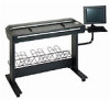
HP Designjet 4200 HP Designjet 4200 Scanner - Assembly and Maintenance Poster - Page 5
Important, camera alignment & calibration - scanner calibration sheet
 |
View all HP Designjet 4200 manuals
Add to My Manuals
Save this manual to your list of manuals |
Page 5 highlights
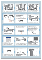
39 40 41 Fit the 'Y' power cable into the clips. Then attach the clips to the stand. Fit the 'Y' power cable and the bundled FireWire cable into the clip. Then attach the clip to the stand. If the touch screen assembly has been mounted on the left, the 'Y' power cable should be attached only to the left leg and the cross bar. 42 camera alignment & calibration 43 (height alignment, stitching, basic calibration, and color calibration) You are now required to calibrate the scanner. For this you will need the scanner maintenance sheet, found in the protective folder shown below. Connect the 'Y' power cable to a power outlet. Switch on the scanner and leave it to warm up for some minutes until the green (ready status) light appears. 44 When the green (ready status) light has appeared, switch on the touch screen. Note: if when switching on the touch screen a 'not present' message appears, please press the 'Rescan' option on the touch screen. Important: make sure that the scanner is turned on for at least one hour before moving on to the next step of camera alignment calibration. Slight light intensity changes and camera shifting can occur just after turning the scanner on, and warm-up time will ensure that light conditions and camera heights have stabilized. 1 hour 45 46 47 To start the maintenance procedure: a) On the touch screen, press the Setup tab. b) Press the Scan Options button. c) Press the Scanner Maintenance button (shown above). 48 The maintenance wizard will ask you to insert the maintenance sheet. The sheet's printed side must be face down. Feed the paper in aligning the two midpoint arrows. Press 'Next' to continue. Now follow the instructions that appear on the touch screen. The scanner comes equipped with two magnetic media guides; these can be placed and moved as required. Insert the plastic caps in the holes in the touch screen arm. When the maintenance procedure has completed, remove the scanner maintenance sheet and return it to its protective cover. Store the folder in a dry place away from light. 5
-
 1
1 -
 2
2 -
 3
3 -
 4
4 -
 5
5 -
 6
6
 |
 |
