HP Designjet 5500 HP Designjet 5500 series printers - Quick Reference Pocket G - Page 45
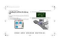
the spindle guides.
 |
View all HP Designjet 5500 manuals
Add to My Manuals
Save this manual to your list of manuals |
Page 45 highlights
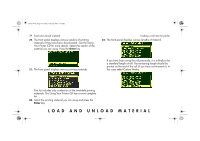
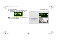
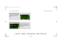
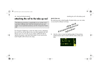
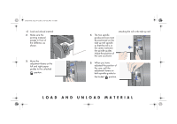
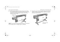
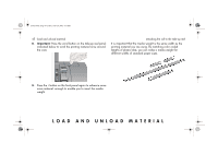
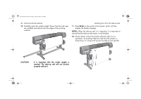
pocket.book Page 43 Friday, June 28, 2002 4:31 PM 43 - load and unload material 2. Make sure the printing material passes in front of the deflector, as shown. 3. Move the adjustment levers on the left and right paper guides to the unlocked position. 4. The two spindle guides and core must be positioned on the take-up reel spindle so that the roll is in the center, between the spindle guides. Adjust the position of the core as shown. attaching the roll to the take-up reel 5. When you have adjusted the position of the core, pull the adjustment levers on both spindle guides to the locked position. LOAD AND UNLOAD MATERIAL
-
 1
1 -
2
-
3
-
4
-
5
-
6
-
7
-
8
-
9
-
10
-
11
-
12
-
13
-
14
-
15
-
16
-
17
-
18
-
19
-
20
-
21
-
22
-
23
-
24
-
25
-
26
-
27
-
28
-
29
-
30
-
31
-
32
-
33
-
34
-
35
-
36
-
37
-
38
-
39
-
 40
40 -
 41
41 -
 42
42 -
 43
43 -
 44
44 -
 45
45 -
 46
46 -
 47
47 -
 48
48 -
 49
49 -
 50
50 -
51
-
52
-
53
-
54
-
55
-
56
-
57
-
58
-
59
-
60
-
61
-
62
-
63
-
64
-
65
-
66
-
67
-
68
-
69
-
70
-
71
-
72
-
73
-
74
-
75
-
76
-
77
-
78
-
79
-
80
-
81
-
82
-
83
-
84
-
85
-
86
-
87
-
88
-
89
-
90
-
91
-
92
-
93
-
94
-
95
-
96
-
97
-
98
-
99
-
100
-
101
-
102
-
103
-
104
-
105
-
106
-
107
-
108
-
109
-
110
-
111
-
112
-
113
-
114
-
115
-
116
-
117
-
118
-
119
-
120
-
121
-
122
-
123
-
124
-
125
-
126
-
127
-
128
-
129
-
130
-
131
-
132
-
133
-
134
-
135
-
136
-
137
-
138
-
139
-
140
-
141
-
142
-
143
-
144
-
145
-
146
-
147
-
148
-
149
-
150
-
151
-
152
-
153
-
154
-
155
-
156
-
157
-
158
-
159
-
160
-
161
-
162
-
163
-
164
-
165
-
166
-
167
-
168
-
169
-
170
-
171
-
172
-
173
-
174
-
175
-
176
-
177
-
178
-
179
-
180
-
181
-
182
-
183
-
184
-
185
-
186
-
187
-
188
-
189
-
190
-
191
-
192
-
193
-
194
-
195
-
196
-
197
-
198
-
199
-
200
-
201
-
202
-
203
-
204
-
205
-
206
-
207
-
208
-
209
-
210
 |
 |
LOAD AND UNLOAD MATERIAL
43 - load and unload material
attaching the roll to the take-up reel
2.
Make sure the
printing material
passes in front of
the deflector, as
shown.
3.
Move the
adjustment levers on the
left and right paper
guides to the unlocked
position.
4.
The two spindle
guides and core must
be positioned on the
take-up reel spindle
so that the roll is in
the center, between
the spindle guides.
Adjust the position of
the core as shown.
5.
When you have
adjusted the position of
the core, pull the
adjustment levers on
both spindle guides to
the locked
position.
pocket.book
Page 43
Friday, June 28, 2002
4:31 PM