HP Dv2 1030us HP Pavilion dv2 Entertainment PC - Maintenance and Service Guide - Page 59
by keyboard icons., Remove one Phillips PM2.5×10.0 screw located in the memory module compartment - how to open
 |
UPC - 884420990550
View all HP Dv2 1030us manuals
Add to My Manuals
Save this manual to your list of manuals |
Page 59 highlights
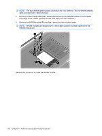
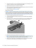
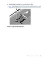
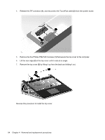
3. Disconnect the power from the computer by first unplugging the power cord from the AC outlet and then unplugging the AC adapter from the computer. 4. Remove the battery (see Battery on page 39). 5. Remove the following components: a. Hard drive (see Hard drive on page 40) b. Memory module (see Memory module on page 43) c. WWAN module (see WWAN module on page 45) d. WLAN module (see WLAN module on page 47) Remove the keyboard: 1. Turn the computer upside down with the front toward you. 2. Remove one Phillips PM2.5×10.0 screw located in the memory module compartment, and one Phillips PM2.5×10.0 screw located in the WLAN compartment. The screw locations are identified by keyboard icons. 3. Turn the computer display-side up, with the front toward you. 4. Open the computer as far as possible. 5. Lift the rear edge of the keyboard (1) until it rests at an angle. Component replacement procedures 51
-
 1
1 -
2
-
3
-
4
-
5
-
6
-
7
-
8
-
9
-
10
-
11
-
12
-
13
-
14
-
15
-
16
-
17
-
18
-
19
-
20
-
21
-
22
-
23
-
24
-
25
-
26
-
27
-
28
-
29
-
30
-
31
-
32
-
33
-
34
-
35
-
36
-
37
-
38
-
39
-
40
-
41
-
42
-
43
-
44
-
45
-
46
-
47
-
48
-
49
-
50
-
51
-
52
-
53
-
 54
54 -
 55
55 -
 56
56 -
 57
57 -
 58
58 -
 59
59 -
 60
60 -
 61
61 -
 62
62 -
 63
63 -
 64
64 -
65
-
66
-
67
-
68
-
69
-
70
-
71
-
72
-
73
-
74
-
75
-
76
-
77
-
78
-
79
-
80
-
81
-
82
-
83
-
84
-
85
-
86
-
87
-
88
-
89
-
90
-
91
-
92
-
93
-
94
-
95
-
96
-
97
-
98
-
99
-
100
-
101
-
102
-
103
-
104
-
105
-
106
-
107
-
108
-
109
-
110
-
111
-
112
-
113
-
114
-
115
-
116
-
117
-
118
-
119
-
120
-
121
-
122
-
123
-
124
-
125
-
126
-
127
-
128
-
129
-
130
-
131
-
132
-
133
-
134
-
135
-
136
-
137
-
138
-
139
-
140
-
141
-
142
-
143
-
144
-
145
-
146
-
147
 |
 |
