HP Dv2 1030us HP Pavilion dv2 Entertainment PC - Maintenance and Service Guide - Page 67
System board, Keyboard see
 |
UPC - 884420990550
View all HP Dv2 1030us manuals
Add to My Manuals
Save this manual to your list of manuals |
Page 67 highlights
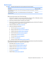
System board NOTE: All system board spare kits include replacement thermal material. Description Spare part number With embedded processor, MV40, 1.6-Ghz, RX781 Northbridge and ATI-M82-S discrete graphics 506763-001 subsystem memory With embedded processor, MV40, 1.6-Ghz, RS780 Northbridge and ATI-M UMA graphics subsystem memory 506762-001 Before removing the system board, follow these steps: 1. Shut down the computer. If you are unsure whether the computer is off or in Hibernation, turn the computer on, and then shut it down through the operating system. 2. Disconnect all external devices connected to the computer. 3. Disconnect the power from the computer by first unplugging the power cord from the AC outlet and then unplugging the AC adapter from the computer. 4. Remove the battery (see Battery on page 39). 5. Remove the following components: a. Hard drive (see Hard drive on page 40) b. Memory module (see Memory module on page 43) c. WWAN module (see WWAN module on page 45) d. WLAN module (see WLAN module on page 47) e. Keyboard (see Keyboard on page 50) f. Top cover (see Top cover on page 53) g. Fan (see Fan on page 55) h. Bluetooth module (see Bluetooth module on page 57) When replacing the system board, be sure that the following components are removed from the defective system board and installed on the replacement system board: ● RTC battery (see RTC battery on page 66) ● Memory module (see Memory module on page 43) ● WWAN module (see WWAN module on page 45) ● WLAN module (see Bluetooth module on page 57) ● Fan (see Fan on page 55) ● Heat sink (see System board on page 59) Component replacement procedures 59
-
 1
1 -
2
-
3
-
4
-
5
-
6
-
7
-
8
-
9
-
10
-
11
-
12
-
13
-
14
-
15
-
16
-
17
-
18
-
19
-
20
-
21
-
22
-
23
-
24
-
25
-
26
-
27
-
28
-
29
-
30
-
31
-
32
-
33
-
34
-
35
-
36
-
37
-
38
-
39
-
40
-
41
-
42
-
43
-
44
-
45
-
46
-
47
-
48
-
49
-
50
-
51
-
52
-
53
-
54
-
55
-
56
-
57
-
58
-
59
-
60
-
61
-
 62
62 -
 63
63 -
 64
64 -
 65
65 -
 66
66 -
 67
67 -
 68
68 -
 69
69 -
 70
70 -
 71
71 -
 72
72 -
73
-
74
-
75
-
76
-
77
-
78
-
79
-
80
-
81
-
82
-
83
-
84
-
85
-
86
-
87
-
88
-
89
-
90
-
91
-
92
-
93
-
94
-
95
-
96
-
97
-
98
-
99
-
100
-
101
-
102
-
103
-
104
-
105
-
106
-
107
-
108
-
109
-
110
-
111
-
112
-
113
-
114
-
115
-
116
-
117
-
118
-
119
-
120
-
121
-
122
-
123
-
124
-
125
-
126
-
127
-
128
-
129
-
130
-
131
-
132
-
133
-
134
-
135
-
136
-
137
-
138
-
139
-
140
-
141
-
142
-
143
-
144
-
145
-
146
-
147
 |
 |
