HP EK430AA User's Guide - HP Plasma HDTV - Page 15
TV rear, Description, Do not connect video cables to both the, S-video and the Video In connectors
 |
View all HP EK430AA manuals
Add to My Manuals
Save this manual to your list of manuals |
Page 15 highlights
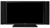
Getting to Know Your TV TV (rear) ■ Speaker R ■ Component 1 Comp 1 Audio In ■ Component 2 Comp 2 Audio In ■ HDMI ■ PC ■ PC/DVI Audio In ■ RS232 ■ Digital Audio Out Description Connect wire from the right speaker. Connect component video cables and left-right audio cables from optional equipment. Supports standard inputs 480i, 480p, 720p, and 1080i. The TV automatically determines what has been connected. Some set-top boxes must be set for a specific resolution out. ■ Connect an HDMI (HighDefinition Multimedia Interface) cable from optional digital, highdefinition equipment. Or ■ Connect a DVI cable and DVI-to-HDMI converter cable from optional DVI equipment; requires an audio cable connected from the DVI equipment to PC/DVI Audio In. Connect a VGA cable from your PC to use the TV as a monitor. ■ Connect an audio cable from the optional PC audio out. Or ■ Connect audio cable from the optional DVI equipment (connected using a DVI cable and DVI-to-HDMI converter cable at the HDMI connector). Used for service purposes only. Connect an optical cable to an external digital audio system. TV (rear) ■ RF Input ■ Video Out Audio Out ■ S-video 1 Video 1 Audio In ■ S-video 2 Video 2 Audio In ■ Video1 In Video 1 Audio In ■ Video 2 In Video 2 Audio In Description (Continued) Connect a coaxial cable from an air antenna or cable signal source. Connect composite video and left-right audio cables to optional equipment for monitoring or recording video. Connect an S-video cable and left-right audio cables from optional equipment. Use Video 1 Audio In for S-video 1, and Video 2 Audio In for S-video 2. (Audio connectors are shared with Video In.) Connect a composite video cable and left-right audio cables from optional equipment. Use Video 1 Audio In for Video 1 In, and Video 2 Audio In for Video 2 In. (Audio connectors are shared with S-video.) ! Do not connect video cables to both the S-video and the Video In connectors in a set. ■ AC In ■ Speaker L Connect the included power cord. NOTE: Use only the provided power cord. Connect wire from the left speaker. Getting to Know Your TV 5
-
 1
1 -
2
-
3
-
4
-
5
-
6
-
7
-
8
-
9
-
 10
10 -
 11
11 -
 12
12 -
 13
13 -
 14
14 -
 15
15 -
 16
16 -
 17
17 -
 18
18 -
 19
19 -
 20
20 -
21
-
22
-
23
-
24
-
25
-
26
-
27
-
28
-
29
-
30
-
31
-
32
-
33
-
34
-
35
-
36
-
37
-
38
-
39
-
40
-
41
-
42
-
43
-
44
-
45
-
46
-
47
-
48
-
49
-
50
-
51
-
52
-
53
-
54
-
55
-
56
-
57
-
58
-
59
-
60
-
61
-
62
-
63
-
64
-
65
-
66
-
67
-
68
-
69
-
70
-
71
-
72
-
73
-
74
-
75
-
76
-
77
-
78
-
79
-
80
-
81
-
82
-
83
-
84
-
85
-
86
-
87
-
88
-
89
-
90
-
91
-
92
-
93
-
94
-
95
-
96
-
97
-
98
-
99
-
100
-
101
-
102
-
103
-
104
-
105
-
106
-
107
-
108
-
109
-
110
-
111
-
112
-
113
-
114
-
115
-
116
-
117
-
118
-
119
-
120
-
121
-
122
-
123
-
124
-
125
-
126
-
127
-
128
-
129
-
130
-
131
-
132
-
133
-
134
-
135
-
136
-
137
-
138
-
139
-
140
-
141
-
142
-
143
-
144
-
145
-
146
-
147
-
148
-
149
-
150
-
151
-
152
-
153
-
154
-
155
-
156
-
157
-
158
-
159
-
160
-
161
-
162
-
163
-
164
-
165
-
166
-
167
-
168
-
169
-
170
-
171
-
172
-
173
-
174
-
175
-
176
-
177
-
178
-
179
-
180
-
181
-
182
-
183
-
184
-
185
-
186
 |
 |
