HP ENVY Notebook - m7-k111dx HP ENVY 17 Notebook PC HP ENVY 15 Notebook PC HP - Page 80
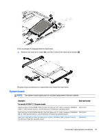
and then remove the system board, Lift the system board
 |
View all HP ENVY Notebook - m7-k111dx manuals
Add to My Manuals
Save this manual to your list of manuals |
Page 80 highlights
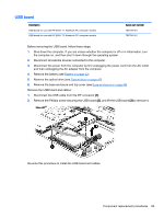
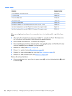
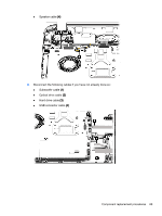
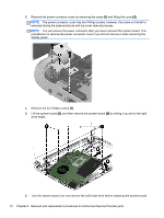
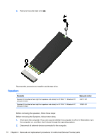
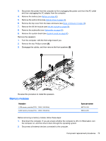
3. Remove the power connector cover by removing the screw (1) and lifting the cover (2). NOTE: The power connector cover has two Phillips screws, however, the screw on the left is removed during the base enclosure and top cover removal process. NOTE: You will remove the power connector after you have removed the system board. This procedure is to remove the power connector cover if you did not remove it when removing the display panel. 4. Remove the six Phillips screws (1). 5. Lift the system board (2), and then remove the system board (3) by sliding it up and to the right at an angle. 6. Turn the system board over and remove the solid sate drive before replacing the system board. 70 Chapter 6 Removal and replacement procedures for Authorized Service Provider parts
-
 1
1 -
2
-
3
-
4
-
5
-
6
-
7
-
8
-
9
-
10
-
11
-
12
-
13
-
14
-
15
-
16
-
17
-
18
-
19
-
20
-
21
-
22
-
23
-
24
-
25
-
26
-
27
-
28
-
29
-
30
-
31
-
32
-
33
-
34
-
35
-
36
-
37
-
38
-
39
-
40
-
41
-
42
-
43
-
44
-
45
-
46
-
47
-
48
-
49
-
50
-
51
-
52
-
53
-
54
-
55
-
56
-
57
-
58
-
59
-
60
-
61
-
62
-
63
-
64
-
65
-
66
-
67
-
68
-
69
-
70
-
71
-
72
-
73
-
74
-
 75
75 -
 76
76 -
 77
77 -
 78
78 -
 79
79 -
 80
80 -
 81
81 -
 82
82 -
 83
83 -
 84
84 -
 85
85 -
86
-
87
-
88
-
89
-
90
-
91
-
92
-
93
-
94
-
95
-
96
-
97
-
98
-
99
-
100
-
101
-
102
-
103
-
104
-
105
-
106
-
107
-
108
-
109
-
110
-
111
-
112
-
113
 |
 |
