HP ENVY m6-aq000 Maintenance and Service Guide - Page 52
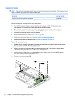
Connector board ZIF connector cable, Speaker cable
 |
View all HP ENVY m6-aq000 manuals
Add to My Manuals
Save this manual to your list of manuals |
Page 52 highlights
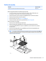
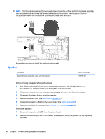
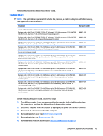
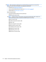
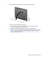
NOTE: When replacing the system board, be sure that the following components are removed from the defective system board and installed on the replacement system board: ● RTC battery (see Bottom cover on page 27) ● Memory module shield and memory module (see Memory module on page 35) ● WLAN module (see WLAN module on page 36) Remove the system board: 1. Disconnect the following cables from the system board: (1) WLAN module antenna cables NOTE: The WLAN "Main/#1"antenna cable is connected to the WLAN module "Main" terminal. The WLAN "Aux/#2"antenna cable is connected to the WLAN module "Aux" terminal. (2) Power connector cable (3) TouchScreen board ZIF connector cable (4) Speaker cable (5) Connector board ZIF connector cable (6) Display panel ZIF connector cable (7) TouchPad board ZIF connector cable (8) Keyboard ZIF connector cable (9) Backlight ZIF connector cable (10) Hard drive ZIF connector cable 44 Chapter 5 Removal and replacement procedures
-
 1
1 -
2
-
3
-
4
-
5
-
6
-
7
-
8
-
9
-
10
-
11
-
12
-
13
-
14
-
15
-
16
-
17
-
18
-
19
-
20
-
21
-
22
-
23
-
24
-
25
-
26
-
27
-
28
-
29
-
30
-
31
-
32
-
33
-
34
-
35
-
36
-
37
-
38
-
39
-
40
-
41
-
42
-
43
-
44
-
45
-
46
-
 47
47 -
 48
48 -
 49
49 -
 50
50 -
 51
51 -
 52
52 -
 53
53 -
 54
54 -
 55
55 -
 56
56 -
 57
57 -
58
-
59
-
60
-
61
-
62
-
63
-
64
-
65
-
66
-
67
-
68
-
69
-
70
-
71
-
72
-
73
-
74
-
75
-
76
-
77
-
78
-
79
-
80
 |
 |
