HP ENVY m6-ar000 Maintenance and Service Guide - Page 41
Remove the Phillips PM2.0×3.8 screw
 |
View all HP ENVY m6-ar000 manuals
Add to My Manuals
Save this manual to your list of manuals |
Page 41 highlights
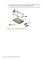
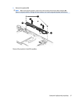
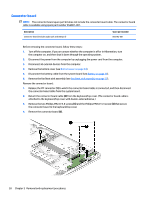
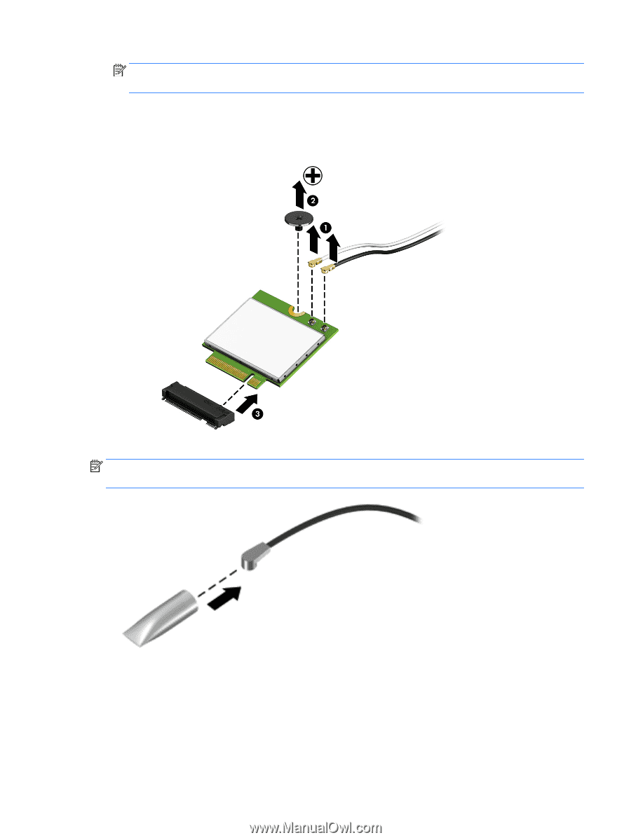
NOTE: The WLAN antenna cable labeled "1/MAIN" connects to the WLAN module "Main" terminal. The WLAN antenna cable labeled "2/AUX" connects to the WLAN module "Aux" terminal. 2. Remove the Phillips PM2.0×3.8 screw (2) that secures the WLAN module to the computer. (The WLAN module tilts up.) 3. Remove the WLAN module (3) by pulling the module away from the slot at an angle. NOTE: If the WLAN antenna cables are not connected to the WLAN module terminal, the protective sleeves should be installed on the antenna connectors, as shown in the following illustration. Reverse this procedure to install the WLAN module. Component replacement procedures 33
-
 1
1 -
2
-
3
-
4
-
5
-
6
-
7
-
8
-
9
-
10
-
11
-
12
-
13
-
14
-
15
-
16
-
17
-
18
-
19
-
20
-
21
-
22
-
23
-
24
-
25
-
26
-
27
-
28
-
29
-
30
-
31
-
32
-
33
-
34
-
35
-
 36
36 -
 37
37 -
 38
38 -
 39
39 -
 40
40 -
 41
41 -
 42
42 -
 43
43 -
 44
44 -
 45
45 -
 46
46 -
47
-
48
-
49
-
50
-
51
-
52
-
53
-
54
-
55
-
56
-
57
-
58
-
59
-
60
-
61
-
62
-
63
-
64
-
65
-
66
-
67
-
68
-
69
-
70
-
71
-
72
-
73
-
74
-
75
-
76
 |
 |
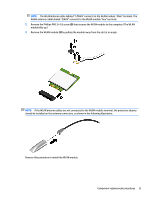
NOTE:
The WLAN antenna cable labeled “1/MAIN” connects to the WLAN module “Main” terminal. The
WLAN antenna cable labeled “2/AUX” connects to the WLAN module “Aux” terminal.
2.
Remove the Phillips PM2.0×3.8 screw
(2)
that secures the WLAN module to the computer. (The WLAN
module tilts up.)
3.
Remove the WLAN module
(3)
by pulling the module away from the slot at an angle.
NOTE:
If the WLAN antenna cables are not connected to the WLAN module terminal, the protective sleeves
should be installed on the antenna connectors, as shown in the following illustration.
Reverse this procedure to install the WLAN module.
Component replacement procedures
33