HP ENVY m6-n000 ENVY m6 Notebook PC ENVY Notebook PC Maintenance and Service G - Page 55
Display assembly, built into the subwoofer.
 |
View all HP ENVY m6-n000 manuals
Add to My Manuals
Save this manual to your list of manuals |
Page 55 highlights
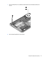
Reverse this procedure to install the base enclosure. Display assembly Description 15.6-in, AntiGlare, FHD, LED, TouchScreen display assembly for use on all computer models 15.6-in, AntiGlare, HD, LED, TouchScreen display assembly for use on all computer models 15.6-in, BrightView, FHD, LED, non-TouchScreen display assembly for use only on computer models equipped with an Intel processor 15.6-in, BrightView, HD, LED, non-TouchScreen display assembly for use only on computer models equipped with an Intel processor Spare part number 788475-001 788474-001 720552-001 720551-001 To remove the display assembly and access the display assembly subcomponents, follow these steps: 1. Turn off the computer. If you are unsure whether the computer is off or in Hibernation, turn the computer on, and then shut it down through the operating system. 2. Disconnect the power from the computer by unplugging the power cord from the computer. 3. Disconnect all external devices from the computer. 4. Remove the battery (see Battery on page 34). 5. Disconnect the wireless antenna cables from the WLAN module (see WLAN module on page 35). 6. Remove the hard drive (see Hard drive on page 38). 7. Remove the base enclosure (see Base enclosure on page 45). Remove the display assembly: 1. Release the wireless antenna cables from the retention clips built into the left rear speaker (1), connector board (2), and top cover (3). 2. Release the wireless antenna cables from the retention clips (4) built into the subwoofer. 3. Release the ZIF connector to which the display panel cable is attached, and then disconnect the display panel cable (5) from the system board. 4. Disconnect the the webcam/microphone module cable (6) from the system board. Component replacement procedures 47
-
 1
1 -
2
-
3
-
4
-
5
-
6
-
7
-
8
-
9
-
10
-
11
-
12
-
13
-
14
-
15
-
16
-
17
-
18
-
19
-
20
-
21
-
22
-
23
-
24
-
25
-
26
-
27
-
28
-
29
-
30
-
31
-
32
-
33
-
34
-
35
-
36
-
37
-
38
-
39
-
40
-
41
-
42
-
43
-
44
-
45
-
46
-
47
-
48
-
49
-
 50
50 -
 51
51 -
 52
52 -
 53
53 -
 54
54 -
 55
55 -
 56
56 -
 57
57 -
 58
58 -
 59
59 -
 60
60 -
61
-
62
-
63
-
64
-
65
-
66
-
67
-
68
-
69
-
70
-
71
-
72
-
73
-
74
-
75
-
76
-
77
-
78
-
79
-
80
-
81
-
82
-
83
-
84
-
85
-
86
-
87
-
88
-
89
-
90
-
91
-
92
-
93
-
94
-
95
-
96
-
97
-
98
-
99
 |
 |