HP EliteBook 650 Maintenance and Service Guide - Page 62
Touchpad, Remove the I/O board
 |
View all HP EliteBook 650 manuals
Add to My Manuals
Save this manual to your list of manuals |
Page 62 highlights
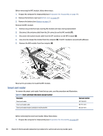
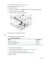
Table 6-3 I/O board description and part number (continued) Description RJ-45 (network) jack door Spare part number M21994-001 Before removing the I/O board, follow these steps: 1. Prepare the computer for disassembly (see Preparation for disassembly on page 41). 2. Remove the bottom cover (see Bottom cover on page 41). 3. Disconnect the battery cable from the system board (see Battery on page 51). Remove the I/O board: 1. Disconnect the cable from the larger ZIF connector (1) and smaller ZIF connector (2) on the I/O board. 2. Remove the three Phillips M2.0 × 4.0 screws (3) that secure the board to the computer, and then remove the network jack door from the board (4). 3. Remove the board from the computer (5). Reverse this procedure to install the I/O board. Touchpad To remove the touchpad, use this procedure and illustration. Table 6-4 Touchpad description and part number Description Touchpad for use in models without NFC Touchpad for use in models with NFC (includes NFC antenna) Touchpad cable (included in Cable Kit) Spare part number N14647-001 M22000-001 N03218-001 54 Chapter 6 Removal and replacement procedures for authorized service provider parts
-
 1
1 -
2
-
3
-
4
-
5
-
6
-
7
-
8
-
9
-
10
-
11
-
12
-
13
-
14
-
15
-
16
-
17
-
18
-
19
-
20
-
21
-
22
-
23
-
24
-
25
-
26
-
27
-
28
-
29
-
30
-
31
-
32
-
33
-
34
-
35
-
36
-
37
-
38
-
39
-
40
-
41
-
42
-
43
-
44
-
45
-
46
-
47
-
48
-
49
-
50
-
51
-
52
-
53
-
54
-
55
-
56
-
 57
57 -
 58
58 -
 59
59 -
 60
60 -
 61
61 -
 62
62 -
 63
63 -
 64
64 -
 65
65 -
 66
66 -
 67
67 -
68
-
69
-
70
-
71
-
72
-
73
-
74
-
75
-
76
-
77
-
78
-
79
-
80
-
81
-
82
-
83
-
84
-
85
-
86
-
87
-
88
-
89
-
90
-
91
-
92
-
93
-
94
-
95
-
96
-
97
-
98
-
99
-
100
-
101
-
102
-
103
-
104
-
105
-
106
-
107
-
108
-
109
-
110
-
111
 |
 |
