HP EliteBook 650 Maintenance and Service Guide - Page 72
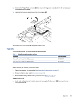
Power connector cable, that secure the speakers to the computer.
 |
View all HP EliteBook 650 manuals
Add to My Manuals
Save this manual to your list of manuals |
Page 72 highlights
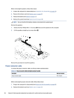
Before removing the speakers, follow these steps: 1. Prepare the computer for disassembly (see Preparation for disassembly on page 41). 2. Remove the bottom cover (see Bottom cover on page 41). 3. Remove the battery (see Battery on page 51). 4. Remove the system board (see System board on page 60). NOTE: Be sure that the RTC battery remains connected to the system board. Remove the speakers: 1. Remove the four Phillips M2.0 × 2.0 screws (1) that secure the speakers to the computer. 2. Lift the speakers straight up to remove them (2). Reverse this procedure to install the speakers. Power connector cable To remove the power connector cable, use this procedure and illustration. Table 6-12 Power connector cable description and part number Description Power connector cable Spare part number M21725-001 Before removing the power connector cable, follow these steps: 1. Prepare the computer for disassembly (see Preparation for disassembly on page 41). 2. Remove the bottom cover (see Bottom cover on page 41). 64 Chapter 6 Removal and replacement procedures for authorized service provider parts
-
 1
1 -
2
-
3
-
4
-
5
-
6
-
7
-
8
-
9
-
10
-
11
-
12
-
13
-
14
-
15
-
16
-
17
-
18
-
19
-
20
-
21
-
22
-
23
-
24
-
25
-
26
-
27
-
28
-
29
-
30
-
31
-
32
-
33
-
34
-
35
-
36
-
37
-
38
-
39
-
40
-
41
-
42
-
43
-
44
-
45
-
46
-
47
-
48
-
49
-
50
-
51
-
52
-
53
-
54
-
55
-
56
-
57
-
58
-
59
-
60
-
61
-
62
-
63
-
64
-
65
-
66
-
 67
67 -
 68
68 -
 69
69 -
 70
70 -
 71
71 -
 72
72 -
 73
73 -
 74
74 -
 75
75 -
 76
76 -
 77
77 -
78
-
79
-
80
-
81
-
82
-
83
-
84
-
85
-
86
-
87
-
88
-
89
-
90
-
91
-
92
-
93
-
94
-
95
-
96
-
97
-
98
-
99
-
100
-
101
-
102
-
103
-
104
-
105
-
106
-
107
-
108
-
109
-
110
-
111
 |
 |
