HP Envy 13-1000 HP ENVY 13 - Maintenance and Service Guide - Page 49
System board, Remove the WLAN module see
 |
View all HP Envy 13-1000 manuals
Add to My Manuals
Save this manual to your list of manuals |
Page 49 highlights
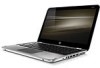
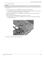
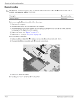
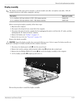
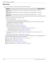
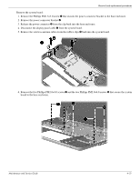
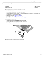
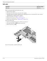
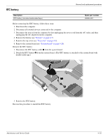
Removal and replacement procedures System board ✎ The system board spare part kit includes replacement thermal material. Description SL9600 system board equipped with an Intel Core2 Duo 2.13-GHz processor (1066-MHz FSB and 6-MB L2 cache) SL9400 system board equipped with an Intel Core2 Duo 1.86-GHz processor (1066-MHz FSB and 6-MB L2 cache) SU9600 system board equipped with an Intel Core2 Duo 1.60-GHz processor (800-MHz FSB and 3-MB L2 cache) Spare part number 538317-001 538316-001 577100-001 Before removing the system board, follow these steps: 1. Shut down the computer. 2. Disconnect all external devices connected to the computer. 3. Disconnect the power from the computer by first unplugging the power cord from the AC outlet, and then unplugging the AC adapter from the computer. 4. Remove the battery (see "Battery" on page 4-7). 5. Remove the top cover (see "Top cover" on page 4-8). 6. Disconnect the following cables from the system board: a. Digital Media Slot board cable (see "Digital Media Slot board" on page 4-12) b. Speaker assembly cable (see "Speaker assembly" on page 4-13) c. Bluetooth module cable (see "Bluetooth module" on page 4-18) 7. Disconnect the mass storage device cable from the mass storage device (see "Mass storage device" on page 4-15). 8. Remove the WLAN module (see "WLAN module" on page 4-16). When replacing the system board, be sure that the following additional components are removed from the defective system board and installed on the replacement system board: ■ Power connector cable (see "Power connector cable" on page 4-23) ■ SATA cable (see "SATA cable" on page 4-24) ■ RTC battery (see "RTC battery" on page 4-25) ■ Memory module (see "Memory module" on page 4-26) ■ Fan/heat sink assembly (see "Fan/heat sink assembly" on page 4-27) 4-20 Maintenance and Service Guide
-
 1
1 -
2
-
3
-
4
-
5
-
6
-
7
-
8
-
9
-
10
-
11
-
12
-
13
-
14
-
15
-
16
-
17
-
18
-
19
-
20
-
21
-
22
-
23
-
24
-
25
-
26
-
27
-
28
-
29
-
30
-
31
-
32
-
33
-
34
-
35
-
36
-
37
-
38
-
39
-
40
-
41
-
42
-
43
-
 44
44 -
 45
45 -
 46
46 -
 47
47 -
 48
48 -
 49
49 -
 50
50 -
 51
51 -
 52
52 -
 53
53 -
 54
54 -
55
-
56
-
57
-
58
-
59
-
60
-
61
-
62
-
63
-
64
-
65
-
66
-
67
-
68
-
69
-
70
-
71
-
72
-
73
-
74
-
75
-
76
-
77
-
78
-
79
-
80
-
81
-
82
-
83
-
84
-
85
-
86
-
87
-
88
-
89
-
90
-
91
-
92
-
93
-
94
-
95
-
96
-
97
-
98
-
99
-
100
-
101
-
102
-
103
-
104
-
105
 |
 |