HP Evo n410c Compaq Evo Notebook N410c Series and N410c Series Maintenance and - Page 112
Switch Cover
 |
View all HP Evo n410c manuals
Add to My Manuals
Save this manual to your list of manuals |
Page 112 highlights
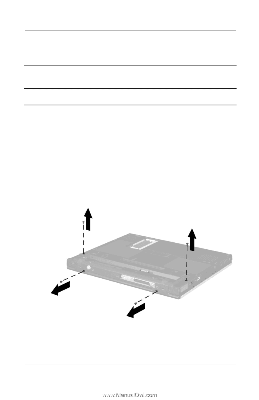
Removal and Replacement Procedures 5.11 Switch Cover Switch Cover Spare Part Number Information Switch cover 231453-001 1. Prepare the notebook for disassembly (Section 5.3). 2. Remove the palm rest (Section 5.5). 3. Remove the keyboard (Section 5.9). 4. Close the notebook. 5. Turn the notebook bottom side up with the rear panel facing forward. 6. Remove the four TM2.0 × 6.0 screws that secure the switch cover to the base enclosure (Figure 5-21). Figure 5-21. Removing the Switch Cover Screws Maintenance and Service Guide 5-27
-
 1
1 -
2
-
3
-
4
-
5
-
6
-
7
-
8
-
9
-
10
-
11
-
12
-
13
-
14
-
15
-
16
-
17
-
18
-
19
-
20
-
21
-
22
-
23
-
24
-
25
-
26
-
27
-
28
-
29
-
30
-
31
-
32
-
33
-
34
-
35
-
36
-
37
-
38
-
39
-
40
-
41
-
42
-
43
-
44
-
45
-
46
-
47
-
48
-
49
-
50
-
51
-
52
-
53
-
54
-
55
-
56
-
57
-
58
-
59
-
60
-
61
-
62
-
63
-
64
-
65
-
66
-
67
-
68
-
69
-
70
-
71
-
72
-
73
-
74
-
75
-
76
-
77
-
78
-
79
-
80
-
81
-
82
-
83
-
84
-
85
-
86
-
87
-
88
-
89
-
90
-
91
-
92
-
93
-
94
-
95
-
96
-
97
-
98
-
99
-
100
-
101
-
102
-
103
-
104
-
105
-
106
-
 107
107 -
 108
108 -
 109
109 -
 110
110 -
 111
111 -
 112
112 -
 113
113 -
 114
114 -
 115
115 -
 116
116 -
 117
117 -
118
-
119
-
120
-
121
-
122
-
123
-
124
-
125
-
126
-
127
-
128
-
129
-
130
-
131
-
132
-
133
-
134
-
135
-
136
-
137
-
138
-
139
-
140
-
141
-
142
-
143
-
144
-
145
-
146
-
147
-
148
-
149
-
150
-
151
-
152
-
153
-
154
-
155
-
156
-
157
-
158
-
159
-
160
-
161
-
162
-
163
-
164
-
165
-
166
-
167
-
168
-
169
-
170
-
171
-
172
 |
 |
Removal and Replacement Procedures
Maintenance and Service Guide
5–27
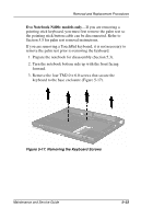
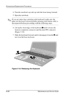
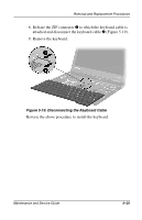
5.11 Switch Cover
1. Prepare the notebook for disassembly (Section 5.3).
2. Remove the palm rest (Section 5.5).
3. Remove the keyboard (Section 5.9).
4. Close the notebook.
5. Turn the notebook bottom side up with the rear panel facing
forward.
6. Remove the four TM2.0 × 6.0 screws that secure the switch
cover to the base enclosure (Figure 5-21).
Figure 5-21. Removing the Switch Cover Screws
Switch Cover
Spare Part Number Information
Switch cover
231453-001