HP Evo n410c Compaq Evo Notebook N410c Series and N410c Series Maintenance and - Page 128
Disconnecting the External Battery Terminal and, NTSC Module Cables from the System Board
 |
View all HP Evo n410c manuals
Add to My Manuals
Save this manual to your list of manuals |
Page 128 highlights
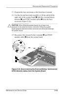
Removal and Replacement Procedures 13. Position the base enclosure so the front faces forward. 14. Use the fan and heat sink assembly to lift up and hold the right side of the system board 1 until the external battery terminal 2 and NTSC module cables 3 clear the base enclosure (Figure 5-34). Ä CAUTION: When lifting the system board, do not exert any pressure on the external monitor connector. Lifting the system board using the external monitor connector can stress and damage the system board. 15. Disconnect the external battery terminal 2 and NTSC module cables 3 from the system board. Figure 5-34. Disconnecting the External Battery Terminal and NTSC Module Cables from the System Board Maintenance and Service Guide 5-43
-
 1
1 -
2
-
3
-
4
-
5
-
6
-
7
-
8
-
9
-
10
-
11
-
12
-
13
-
14
-
15
-
16
-
17
-
18
-
19
-
20
-
21
-
22
-
23
-
24
-
25
-
26
-
27
-
28
-
29
-
30
-
31
-
32
-
33
-
34
-
35
-
36
-
37
-
38
-
39
-
40
-
41
-
42
-
43
-
44
-
45
-
46
-
47
-
48
-
49
-
50
-
51
-
52
-
53
-
54
-
55
-
56
-
57
-
58
-
59
-
60
-
61
-
62
-
63
-
64
-
65
-
66
-
67
-
68
-
69
-
70
-
71
-
72
-
73
-
74
-
75
-
76
-
77
-
78
-
79
-
80
-
81
-
82
-
83
-
84
-
85
-
86
-
87
-
88
-
89
-
90
-
91
-
92
-
93
-
94
-
95
-
96
-
97
-
98
-
99
-
100
-
101
-
102
-
103
-
104
-
105
-
106
-
107
-
108
-
109
-
110
-
111
-
112
-
113
-
114
-
115
-
116
-
117
-
118
-
119
-
120
-
121
-
122
-
 123
123 -
 124
124 -
 125
125 -
 126
126 -
 127
127 -
 128
128 -
 129
129 -
 130
130 -
 131
131 -
 132
132 -
 133
133 -
134
-
135
-
136
-
137
-
138
-
139
-
140
-
141
-
142
-
143
-
144
-
145
-
146
-
147
-
148
-
149
-
150
-
151
-
152
-
153
-
154
-
155
-
156
-
157
-
158
-
159
-
160
-
161
-
162
-
163
-
164
-
165
-
166
-
167
-
168
-
169
-
170
-
171
-
172
 |
 |

Removal and Replacement Procedures
Maintenance and Service Guide
5–43
13. Position the base enclosure so the front faces forward.
14. Use the fan and heat sink assembly to lift up and hold the
right side of the system board
1
until the external battery
terminal
2
and NTSC module cables
3
clear the base
enclosure (Figure 5-34).
Ä
CAUTION:
When lifting the system board, do not exert any
pressure on the external monitor connector. Lifting the system
board using the external monitor connector can stress and damage
the system board.
15. Disconnect the external battery terminal
2
and NTSC
module cables
3
from the system board.
Figure 5-34. Disconnecting the External Battery Terminal and
NTSC Module Cables from the System Board