HP Folio 13-1020us HP Folio 13 - Maintenance and Service Guide - Page 45
Remove the display panel, right speaker clips
 |
View all HP Folio 13-1020us manuals
Add to My Manuals
Save this manual to your list of manuals |
Page 45 highlights
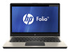
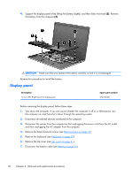
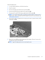
Remove the display panel: 1. Turn the computer right-side up, with the front toward you. 2. Open the computer. 3. Disconnect the display panel cable from the system board (1). 4. Disconnect the USB/Audio board cable from the system board (2). 5. Disconnect the #1 and #2 WLAN antenna cables from the WLAN module (3). NOTE: The #1 WLAN antenna cable is connected to the WLAN module #1 terminal. The #2 WLAN antenna cable is connected to the WLAN module #2 terminal. For more information, see WLAN module on page 38, 6. Ensure that the cables are released from the routing clips, the interior computer channels, and the right speaker clips (4). 7. Remove the 5 screws (1) securing the display panel to the computer. There are 3 screws on the left hinge and 2 screws on the right hinge. NOTE: Support the display panel as you are removing the screws. Component replacement procedures 37
-
 1
1 -
2
-
3
-
4
-
5
-
6
-
7
-
8
-
9
-
10
-
11
-
12
-
13
-
14
-
15
-
16
-
17
-
18
-
19
-
20
-
21
-
22
-
23
-
24
-
25
-
26
-
27
-
28
-
29
-
30
-
31
-
32
-
33
-
34
-
35
-
36
-
37
-
38
-
39
-
 40
40 -
 41
41 -
 42
42 -
 43
43 -
 44
44 -
 45
45 -
 46
46 -
 47
47 -
 48
48 -
 49
49 -
 50
50 -
51
-
52
-
53
-
54
-
55
-
56
-
57
-
58
-
59
-
60
-
61
-
62
-
63
-
64
-
65
-
66
-
67
-
68
-
69
-
70
-
71
-
72
-
73
-
74
-
75
-
76
-
77
-
78
-
79
-
80
-
81
-
82
-
83
-
84
-
85
-
86
 |
 |