HP Folio 13-1020us HP Folio 13 - Maintenance and Service Guide - Page 47
Remove the Phillips PM 2.0×2.5 screw, WLAN modules are designed with a notch
 |
View all HP Folio 13-1020us manuals
Add to My Manuals
Save this manual to your list of manuals |
Page 47 highlights
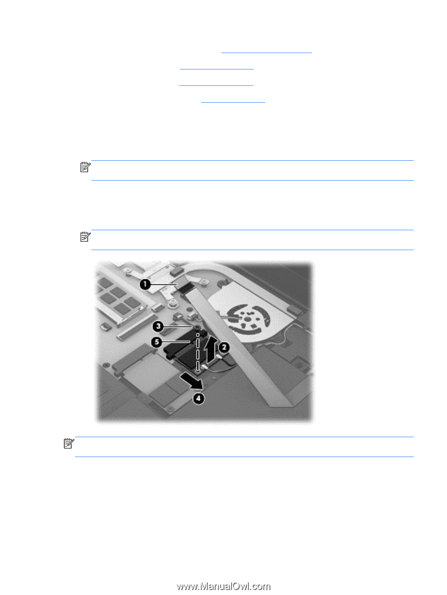
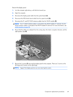
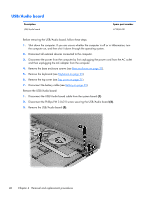
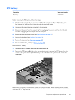
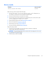
4. Remove the base enclosure screws (see Base enclosure on page 27). 5. Remove the keyboard (see Keyboard on page 29). 6. Remove the top cover (see Top cover on page 31). 7. Disconnect the battery cable (see Battery on page 35). Remove the WLAN module: 1. Disconnect the USB/Audio board cable from the system board (1). 2. Disconnect the #1 and #2 WLAN antenna cables from the WLAN module. NOTE: The #1 WLAN antenna cable is connected to the WLAN module #1 terminal. The #2 WLAN antenna cable is connected to the WLAN module #2 terminal. 3. Remove the Phillips PM 2.0×2.5 screw (3) that secures the WLAN module to the system board. (The WLAN module tilts up.) 4. Remove the WLAN module by pulling the module away from the slot at an angle (4). NOTE: WLAN modules are designed with a notch (5) to prevent incorrect insertion into the memory module slot. NOTE: If the WLAN antennas are not connected to the terminals on the WLAN module, the protective sleeves must be installed on the antenna connectors. Component replacement procedures 39
-
 1
1 -
2
-
3
-
4
-
5
-
6
-
7
-
8
-
9
-
10
-
11
-
12
-
13
-
14
-
15
-
16
-
17
-
18
-
19
-
20
-
21
-
22
-
23
-
24
-
25
-
26
-
27
-
28
-
29
-
30
-
31
-
32
-
33
-
34
-
35
-
36
-
37
-
38
-
39
-
40
-
41
-
 42
42 -
 43
43 -
 44
44 -
 45
45 -
 46
46 -
 47
47 -
 48
48 -
 49
49 -
 50
50 -
 51
51 -
 52
52 -
53
-
54
-
55
-
56
-
57
-
58
-
59
-
60
-
61
-
62
-
63
-
64
-
65
-
66
-
67
-
68
-
69
-
70
-
71
-
72
-
73
-
74
-
75
-
76
-
77
-
78
-
79
-
80
-
81
-
82
-
83
-
84
-
85
-
86
 |
 |