HP Indigo 10000 Electronics Reference Document -- CA493-01140 Rev 00 - Page 15
Power distribution controller PDC, N14V after Resetable Fuse is OK
 |
View all HP Indigo 10000 manuals
Add to My Manuals
Save this manual to your list of manuals |
Page 15 highlights
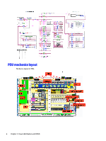
Position in picture 20 21 22 23 24 25 26 27 28 29 30 31 32 33 34 35 36 37 38 39 40 41 42 43 44 45 46 47 48 49 50 51 52 53 54 LED DS20 DS21 DS22 DS23 DS24 DS25 DS26 DS27 DS28 DS29 DS30 DS31 DS32 DS33 DS34 DS35 DS36 DS37 DS38 DS39 DS40 DS41 DS42 DS43 DS44 DS45 DS46 DS47 DS48 DS49 DS50 DS51 DS52 DS53 DS54 PDC function CPU LED (BOARD_OK) CPU LED (CAN2_Error) CPU LED (Debug) CPU LED (BOARD_Errror) N14V Supply is OK N14V after Resetable Fuse is OK 48V UPS is OK 1.45V for CPU is OK 24V_F0 supply is OK Mains Phases in TROUBLE DC/DC0 9-27V Enable DC/DC0 9-27V Voltage exists MOTOR1 runs Backward Mains Phase T presents MOTOR1 runs Forward Mains Phase S presents Mains Phase S presents 2.5V supply is OK 1.2V supply is OK PLC_INTERLOCK0 Active PLC_INTERLOCK4 Active Onboard Relay Activated 24V AC presents PLC_INTERLOCK1 Active PLC_INTERLOCK5 Active PLC_INTERLOCK2 Active MCN INTERLOCK Active PLC_INTERLOCK3 Active MOTOR2 runs Backward 24V_F1 supply is OK Low Side 1A output0 activated Low Side 1A output1 activated Low Side 1A output4 activated Low Side 1A output5 activated Low Side 1A output16 activated Power distribution controller (PDC) 11
-
 1
1 -
2
-
3
-
4
-
5
-
6
-
7
-
8
-
9
-
 10
10 -
 11
11 -
 12
12 -
 13
13 -
 14
14 -
 15
15 -
 16
16 -
 17
17 -
 18
18 -
 19
19 -
 20
20 -
21
-
22
-
23
-
24
-
25
-
26
-
27
-
28
-
29
-
30
-
31
-
32
-
33
-
34
-
35
-
36
-
37
-
38
-
39
-
40
-
41
-
42
-
43
-
44
-
45
-
46
-
47
-
48
-
49
-
50
-
51
-
52
-
53
-
54
-
55
-
56
-
57
-
58
-
59
-
60
-
61
-
62
-
63
-
64
-
65
-
66
-
67
-
68
 |
 |
