Table of contents
1 Overview
................................................................................................................................................................................
1
Utility cabinet – wiring summary
......................................................................................................................................
1
PE/UC cross connection
.....................................................................................................................................................
1
2
Turning the press off and on
..................................................................................................................................................
3
Turning off the press
.........................................................................................................................................................
3
Turning on the press
..........................................................................................................................................................
3
3
Power distribution unit (PDU)
................................................................................................................................................
4
Overview
............................................................................................................................................................................
4
PDU block diagram
............................................................................................................................................................
5
Circuit breakers (CBs) power path
.....................................................................................................................................
5
PDU mechanics layout
.......................................................................................................................................................
6
PDU contacts and circuit breakers (CBs)
...........................................................................................................................
7
PDU right door lamps
........................................................................................................................................................
7
Power distribution control
.................................................................................................................................................
8
Dimmers
...........................................................................................................................................................................
16
Solid state relay (SSR)
.....................................................................................................................................................
17
Electronics cabinet power (ECP)
......................................................................................................................................
18
Electrical cabinet
.............................................................................................................................................................
23
Power supplies (PS)
.........................................................................................................................................................
24
DC distributor (DCD) MR2
.................................................................................................................................................
25
Electronic monitor relay (EMR)
........................................................................................................................................
26
Switches
...........................................................................................................................................................................
27
Hubs
.................................................................................................................................................................................
28
4
B&R system
..........................................................................................................................................................................
30
Main subsystem controlled by B&R
.................................................................................................................................
30
Communications
..............................................................................................................................................................
30
B&R connection map
.......................................................................................................................................................
30
MR2 B&R PL and link bus receiver-transmitter module (X2X) block diagram
................................................................
31
MR2 drivers enabled according to groups
.......................................................................................................................
31
Electrical cabinet
.............................................................................................................................................................
32
PC automation
.................................................................................................................................................................
33
Electronics cabinet input output (ECIO) board and block diagram
.................................................................................
33
ECIO LEDs layout for status indication
............................................................................................................................
34
ii
 1
1 2
2 3
3 4
4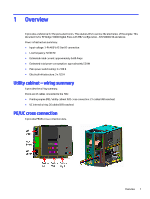 5
5 6
6 7
7 8
8

