HP Indigo 7800 Leak Valves Flow Calibration -- CA393-08710 Rev 01 - Page 8
Calibrating the flow of the air flow leak valve
 |
View all HP Indigo 7800 manuals
Add to My Manuals
Save this manual to your list of manuals |
Page 8 highlights
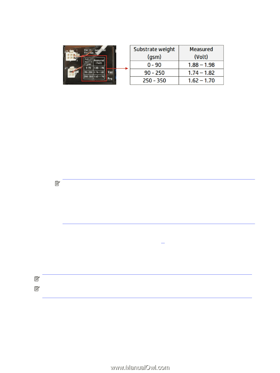
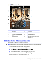
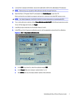
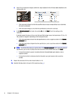
d. Check if your measured voltage is within the range indicated in the reference table attached to the valves power box: ● If the measured voltage is within the specified values range corresponding to your substrate, the valve is calibrated. ● If the measured voltage is not within the specifications, proceed to next step. e. In the Current command field, enter the number 5 and click Send. Check the reading on the voltmeter. If needed, repeat this step until you reach the specified voltage range. Use increments of 5 (i.e., 10, 15), positive or negative, depending on the measured results: ● If the measured value is lower than the specifications, enter a negative number in the Current command field. ● If the measured value is higher than the specifications, enter a positive number in the Current command field. NOTE: To estimate the value you need to enter in the Current command field to reach the relevant specification, you can also visually check the movement of the shutter when you click Send. ● To move the shutter in counter-clockwise direction (towards higher gsm values), enter a negative number. ● To move the shutter in clockwise direction (towards lower gsm values), enter a positive number. 10. Repeat the procedure for the other drawer (either 2 or 3). 11. Reattach the blue tube to the port of the valve (see step 4.). Calibrating the flow of the air flow leak valve Follow these steps to calibrate the flow of the air flow leak valve. NOTE: To perform this procedure the CE needs a voltmeter and a laptop with the FDT software installed. NOTE: If you have previously calibrated the vacuum valve, you do not need to run again the wizard that performs the home position calibration in Print Care. 1. Open the panel at the rear of the feeder to reach the leak valve. 2. Insert the probes of the voltmeter into the J2 connector: match red probe with red wire and black probe with black wire. 3. Detach the blue tube from the port of the valve that you are NOT calibrating. (In this case, detach the tube from the Vacuum port). 6 Chapter 2 Procedures
-
 1
1 -
2
-
 3
3 -
 4
4 -
 5
5 -
 6
6 -
 7
7 -
 8
8 -
 9
9 -
 10
10 -
 11
11 -
 12
12
 |
 |