HP Indigo 7800 Leak Valves Flow Calibration -- CA393-08710 Rev 01 - Page 9
HP Indigo 7800 Manual
 |
View all HP Indigo 7800 manuals
Add to My Manuals
Save this manual to your list of manuals |
Page 9 highlights
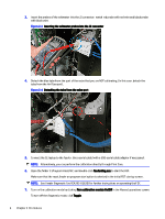
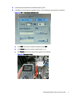
4. Connect the CE laptop to the feeder. Use a serial cable (with a USB-serial cable adaptor if necessary). NOTE: Alternatively, you can perform the calibration directly through Print Care. 5. Open the folder C:\Program Files\FDT, and double-click feederdiag.exe to start the FDT. Make sure that the reset feeder on program start option is selected in the initial FDT startup screen. NOTE: See Feeder Diagnostic Tool (CA393-02630) for further instructions on operating the FDT. 6. Turn on the calibration mode by clicking Turn calibration module On/Off in the Manual operations screen. To turn off the diagnostic mode, click Toggle. 7. Load 90 gsm gloss substrate into the feeder drawers 2 and 3. 8. In the FDT, go to the Air pressure calibration area to set the parameters and perform the calibration. Figure 2-7 FDT - Air pressure calibration area a. In the GSM drop-down list, select the substrate weight 090. b. In the Drawer field, enter a drawer number (either 2 or 3). c. Click Airflow and view the measurement results on the voltmeter. Calibrating the flow of the air flow leak valve 7
-
 1
1 -
2
-
3
-
 4
4 -
 5
5 -
 6
6 -
 7
7 -
 8
8 -
 9
9 -
 10
10 -
 11
11 -
 12
12
 |
 |
