HP Integrity Superdome 2 HP Integrity Superdome 2 Site Preparation Guide (AH33
HP Integrity Superdome 2 Manual
 |
View all HP Integrity Superdome 2 manuals
Add to My Manuals
Save this manual to your list of manuals |
HP Integrity Superdome 2 manual content summary:
- HP Integrity Superdome 2 | HP Integrity Superdome 2 Site Preparation Guide (AH33 - Page 1
HP Integrity Superdome 2 Site Preparation Guide HP Part Number: AH337-9006A Published: August 2010 Edition: 1 - HP Integrity Superdome 2 | HP Integrity Superdome 2 Site Preparation Guide (AH33 - Page 2
to change without notice. The only warranties for HP products and services are set forth in the express warranty statements accompanying such products and services. Nothing herein should be construed as constituting an additional warranty. HP shall not be liable for technical or editorial errors - HP Integrity Superdome 2 | HP Integrity Superdome 2 Site Preparation Guide (AH33 - Page 3
LED...16 Onboard Administrator LEDs and buttons 16 HP Integrity Superdome 2 Onboard Administrator module components 17 XFM LEDs and components...18 GPSM LEDs and components...19 DVD module LEDs and components 21 Interconnect bay numbering...21 Server blade overview...22 Server blade components - HP Integrity Superdome 2 | HP Integrity Superdome 2 Site Preparation Guide (AH33 - Page 4
Installing HP Insight Remote Support Software 40 Related information...41 Typographic conventions...41 Customer self repair...41 Standard terms, abbreviations, and acronyms 43 Index...46 4 Table of Contents - HP Integrity Superdome 2 | HP Integrity Superdome 2 Site Preparation Guide (AH33 - Page 5
fabric that supports partitioning of server blade resources in both nPartitions and virtual partitions. Superdome 2 also includes remote system management functionality through the HP Onboard Administrator which helps monitor and manage complex resources, including partitioning. NOTE: HP Integrity - HP Integrity Superdome 2 | HP Integrity Superdome 2 Site Preparation Guide (AH33 - Page 6
supports only DDR3 SDRAM technology using industry-standard 1.2" high DIMMs. Single DIMM CB900s i2 Min / Max sizes Memory size 4 GB 8 GB1 32 GB / 128GB 64 GB / 256 GB 1 8 GB DIMMs available in Q4 2010. For more DIMM information, see the HP Integrity Superdome 2 User Service Guide. 6 HP - HP Integrity Superdome 2 | HP Integrity Superdome 2 Site Preparation Guide (AH33 - Page 7
compute enclosure. For more information, see the HP Integrity Superdome 2 User Service Guide. I/O expansion enclosure HP Integrity Superdome 2 complexes support up to eight IOX enclosures (four in SD2-8s complexes) to provide additional I/O for server blades through Flex-connect cables from the XFMs - HP Integrity Superdome 2 | HP Integrity Superdome 2 Site Preparation Guide (AH33 - Page 8
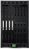
Component overview Compute enclosure overview Compute enclosure front components Item 1 2 3 4 5 6 7 8 HP Integrity Superdome 2 system overview Description Power supply bay 7 Power supply bay 8 Power supply bay 9 Power supply bay 10 Power supply bay 11 Power supply bay 12 DVD module - HP Integrity Superdome 2 | HP Integrity Superdome 2 Site Preparation Guide (AH33 - Page 9
6 10 Power supply bay 5 11 Insight Display 12 Power supply bay 4 13 Power supply bay 3 14 Power supply bay 2 15 Power supply bay 1 16 Device bays1 17 Air intake slot (DO NOT BLOCK) 1 For more information, see "Device bay numbering" (page 10). Power supply bay numbering Component - HP Integrity Superdome 2 | HP Integrity Superdome 2 Site Preparation Guide (AH33 - Page 10
rear of the enclosure. Be sure to review device bay numbering to determine which external network connections on the interconnect modules are active. IOX enclosures are external and connected to the XFMs in compute enclosures through Flex-connect cables. 10 HP Integrity Superdome 2 system overview - HP Integrity Superdome 2 | HP Integrity Superdome 2 Site Preparation Guide (AH33 - Page 11
IMPORTANT: When looking at the rear of the enclosure, device bay numbering is reversed. Server blade device bay numbering Component overview 11 - HP Integrity Superdome 2 | HP Integrity Superdome 2 Site Preparation Guide (AH33 - Page 12
HP Integrity Superdome 2 Insight Display components Item Description Function 1 Insight Display screen Displays Main Menu error messages and instructions 2 Left arrow button Moves the menu or navigation bar selection left one position 3 Right arrow button Moves the menu or navigation - HP Integrity Superdome 2 | HP Integrity Superdome 2 Site Preparation Guide (AH33 - Page 13
Compute enclosure rear components Item Description 1 ac power connectors (upper) 2 Fan bay 1 3 Fan bay 6 4 Fan bay 2 5 Fan bay 7 6 Fan bay 3 7 Fan bay 8 8 Fan bay 4 9 Fan bay 9 Component overview 13 - HP Integrity Superdome 2 | HP Integrity Superdome 2 Site Preparation Guide (AH33 - Page 14
ac power connectors (lower) 25 Fan bay 15 26 Fan bay 14 27 Fan bay 13 28 Fan bay 12 29 Fan bay 11 30 Onboard Administrator bay 1 31 Interconnect bay 7 32 Interconnect bay 5 33 Interconnect bay 3 34 Interconnect bay 1 35 GPSM bay 1 14 HP Integrity Superdome 2 system overview - HP Integrity Superdome 2 | HP Integrity Superdome 2 Site Preparation Guide (AH33 - Page 15
Fan bay numbering Component overview 15 - HP Integrity Superdome 2 | HP Integrity Superdome 2 Site Preparation Guide (AH33 - Page 16
is working. The fan has failed. See the Insight Display screen. Item 1 2 3 4 5 16 HP Integrity Superdome 2 system overview Description Onboard Administrator UID LED Enclosure UID LED and UID button Onboard Administrator health LED Onboard Administrator active LED Onboard Administrator reset button - HP Integrity Superdome 2 | HP Integrity Superdome 2 Site Preparation Guide (AH33 - Page 17
HP Integrity Superdome 2 Onboard Administrator module components Item Name Description 1 Reset button - 2 OA/iLO management port Ethernet 100BaseT RJ45 connector, which provides Ethernet access to the Onboard Administrator and the iLO on each blade. Also supports interconnect modules - HP Integrity Superdome 2 | HP Integrity Superdome 2 Site Preparation Guide (AH33 - Page 18
-connect port 7 16 Link Cable Status LED 7 17 XFM Flex-connect port 8 18 Link Cable Status LED 8 19 Health LED 18 HP Integrity Superdome 2 system overview Description Blue = UID on Indicates if the module is powered on. Green = On Indicates the status of the Xbar Fabric link.1 Indicates - HP Integrity Superdome 2 | HP Integrity Superdome 2 Site Preparation Guide (AH33 - Page 19
Item Name Description Flashing red = Critical error 1 Solid green = Link OK, transmitting at full bandwidth Flashing green = Link OK, no activity Solid yellow = No link Alternating green/yellow = Link OK, transmitting at reduced bandwidth CAUTION: If the Link Cable Status LED is green, flashing - HP Integrity Superdome 2 | HP Integrity Superdome 2 Site Preparation Guide (AH33 - Page 20
connected or connected incorrectly 14 Global clock connector 3 15 Global clock connector 2 16 Global clock connector 1 17 Enclosure DVD module USB connector NOTE: To ensure proper Link established with activity, but collisions are detected 20 HP Integrity Superdome 2 system overview - HP Integrity Superdome 2 | HP Integrity Superdome 2 Site Preparation Guide (AH33 - Page 21
LED 4 Tray open/close button 5 Manual tray release 6 Health LED Green = OK Flashing yellow = Critical error 7 UID LED Blue = UID on Interconnect bay numbering To support server blade LOM and mezzanine card network connections for specific signals, install the interconnect module into the - HP Integrity Superdome 2 | HP Integrity Superdome 2 Site Preparation Guide (AH33 - Page 22
For detailed port mapping information, see the HP Integrity Superdome 2 User Service Guide. Server blade overview Server blade components Item 1 2 3 4 5 6 22 HP Integrity Superdome 2 system overview Description CPU 1 socket power connector CPU 1 socket Agent baffle Agent ASIC 1 Agent ASIC 0 Center - HP Integrity Superdome 2 | HP Integrity Superdome 2 Site Preparation Guide (AH33 - Page 23
2 (Type 2) Mezzanine connector 1 (Type 1) Mezzanine connector 3 (Type 2) Battery sockets (2) IOH ASIC CPU 0 socket Lower air baffle CPU 0 socket power connector DDR3 DIMM slots (32) SUV connector Server blade release levers (2) Server blade release buttons (2) Serial label pull tab SUV board Item - HP Integrity Superdome 2 | HP Integrity Superdome 2 Site Preparation Guide (AH33 - Page 24
NIC. Solid green = Network linked, no activity Flashing green = Network linked, activity 7 Power LED Indicates if the server blade is powered on and active. Green = Powered on and active Flashing yellow = Powered on, not active 8 SUV connector 24 HP Integrity Superdome 2 system overview - HP Integrity Superdome 2 | HP Integrity Superdome 2 Site Preparation Guide (AH33 - Page 25
connection. Be careful when walking near the server blade when the SUV cable is installed. Hitting or bumping the cable might cause the port on the server blade to break and damage the system board. 1 Server blade 2 Video IOX enclosure overview IOX enclosure front view 3 USB ports (2) 4 Serial - HP Integrity Superdome 2 | HP Integrity Superdome 2 Site Preparation Guide (AH33 - Page 26
1 Link Cable Status LEDs 2 CAMNet connector 1 3 Power supply 1 4 Power supply 2 5 CAMNet connector 2 26 HP Integrity Superdome 2 system overview Description Indicates the status of the Xbar Fabric link. Solid green = Link OK, transmitting at full bandwidth Flashing green = Link OK, no - HP Integrity Superdome 2 | HP Integrity Superdome 2 Site Preparation Guide (AH33 - Page 27
Item Name Description 6 I/O bay 2 PCIe slots 7 Flex-connect connectors (6) NOTE: Flex-connect ports 2 and 5 are not used. 8 I/O bay 1 PCIe slots Each CAMNet connector has a Collision LED and an Activity LED. Collision LED Off Steady Green Steady green Flashing green Activity LED Off - HP Integrity Superdome 2 | HP Integrity Superdome 2 Site Preparation Guide (AH33 - Page 28
IOX enclosure components Item 1 2 3 4 5 6 7 8 9 10 11 12 28 HP Integrity Superdome 2 system overview Description I/O bay 2 OL* board Power supplies (2) I/O bay 1OL* board PCIe slot release latches (12) PCIe card slots (12) SAS battery location Fan 4 Fan 3 I/O - HP Integrity Superdome 2 | HP Integrity Superdome 2 Site Preparation Guide (AH33 - Page 29
Slot is powered on and normal Slot is powering down CAUTION: If the Power LED is lit, do not open the latch or attempt to install or remove a PCIe card. NOTE: The Power and Attention LEDs are also visible from the rear of the - HP Integrity Superdome 2 | HP Integrity Superdome 2 Site Preparation Guide (AH33 - Page 30
enclosure Server blade I/O expansion enclosure Width (in/cm) 17.6/44.7 2.02/5.13 17.2/43.7 Depth (in/cm) 32.6/82.8 19.69/50.01 22.4/56.9 Height (in/cm) 31.4/79.8 24.48/62.18 6.9/17.4 For information on the dimensions of HP 10000 G2 Series racks, see the HP 10000 G2 Series User Guide. Component - HP Integrity Superdome 2 | HP Integrity Superdome 2 Site Preparation Guide (AH33 - Page 31
Part number 8120-6895 8120-6897 8121-0070 8120-6903 Description Stripped end, 240 V Male IEC309, 240 V Male GB-1002, 240 V Japan Table 2-6 Compute enclosure single-phase HP 2400 W High Efficiency power supply specifications Specification Power 10 ms 1.16 mA 0.98 Electrical specifications 31 - HP Integrity Superdome 2 | HP Integrity Superdome 2 Site Preparation Guide (AH33 - Page 32
enclosure 3-phase HP 2400 W power IEC-309 220-240V, 5-pin, 16 A 3.0m (10ft) 12.1 User expected maximum power1 Watts 8820 VA 9000 1 Typical maximum Power: or User highly unlikely that any real-world application will result in this amount of power use for any significant time period. Table 2-10 IOX - HP Integrity Superdome 2 | HP Integrity Superdome 2 Site Preparation Guide (AH33 - Page 33
about general site preparation guidelines, see the Generic Site Preparation Guide. Environmental specifications Temperature and humidity specifications The following table contains the allowed and recommended temperature and humidity limits for both operating and non-operating Superdome 2 systems - HP Integrity Superdome 2 | HP Integrity Superdome 2 Site Preparation Guide (AH33 - Page 34
Cooling requirements HP Integrity Superdome 2 is a rack mounted system that cools by drawing air in the front and exhausting it out the rear. General ASHRAE best practices must be followed when installing Superdome 2 in a data center: • Hot/cold aisle layout • Fully blank any unused space in the - HP Integrity Superdome 2 | HP Integrity Superdome 2 Site Preparation Guide (AH33 - Page 35
temperatures exceeding the specified inlet air temperature maximum of 32° C, proper operation above this point is not guaranteed. Because the airflow/watt is quite low for Superdome 2, the exhaust air temperature is, by design, quite high. The following is a chart that shows exhaust air temperature - HP Integrity Superdome 2 | HP Integrity Superdome 2 Site Preparation Guide (AH33 - Page 36
is the parameter of interest to meet the 15-32° C limits for the proper operation of Superdome2, the return air set-point may need to be site preparation guidelines, see the Generic Site Preparation Guide. Air quality specifications Chemical contaminant levels in customer environments for HP - HP Integrity Superdome 2 | HP Integrity Superdome 2 Site Preparation Guide (AH33 - Page 37
within the computer room when adding HP Integrity Superdome 2 systems to computer rooms with existing noise sources. For more information about general site preparation guidelines, see the Generic Site Preparation Guide. Sample Site Inspection Checklist for Site Preparation See Table 2-13 and Table - HP Integrity Superdome 2 | HP Integrity Superdome 2 Site Preparation Guide (AH33 - Page 38
Site 16. Does the input frequency correspond to equipment specifications? 17. Are lightning arrestors installed inside the building? 18. Is power conditioning equipment installed computer room have antistatic flooring installed? 26. Do any equipment servicing hazards exist (loose ground wires - HP Integrity Superdome 2 | HP Integrity Superdome 2 Site Preparation Guide (AH33 - Page 39
32. Is shelving available for documentation? Training Number Area or Condition 33. Are personnel enrolled in the System Administrator's Course? 34. Is on-site training required? Comment or Date For more information about general site preparation guidelines, see the Generic Site Preparation - HP Integrity Superdome 2 | HP Integrity Superdome 2 Site Preparation Guide (AH33 - Page 40
of HP. Installing HP Insight Remote Support Software HP strongly recommends that you install HP Insight Remote Support software to complete the installation or upgrade of your product and to enable improved delivery of your HP Warranty, HP Care Pack Service or HP contractual support agreement. HP - HP Integrity Superdome 2 | HP Integrity Superdome 2 Site Preparation Guide (AH33 - Page 41
information: • HP Integrity Superdome 2 Onboard Administrator User Guide • HP Integrity Superdome 2 Onboard Administrator Command Line Interface User Guide • HP Integrity Superdome 2 Partitioning Administrator Guide You can find these documents from the Manuals page of the HP Business Support Center - HP Integrity Superdome 2 | HP Integrity Superdome 2 Site Preparation Guide (AH33 - Page 42
shipping and part return costs and determine the courier/carrier to be used. For more information about the HP Customer Self Repair program, contact your local service provider. For the North American program, visit the HP website (http://www.hp.com/go/ selfrepair). 42 Support and other resources - HP Integrity Superdome 2 | HP Integrity Superdome 2 Site Preparation Guide (AH33 - Page 43
specific integrated circuit. Battery-backed RAM. Battery-backed write cache. Boot console handler. CAMnet completer module. Customer engineer. Core system. Extensible firmware interface. See also UEFI.. Event management service. Electrostatic discharge. Fibre channel. Forward progress log. Field - HP Integrity Superdome 2 | HP Integrity Superdome 2 Site Preparation Guide (AH33 - Page 44
partition. Integrated Lights-Out 3. I/O expansion enclosure. Itanium processor family. Lightweight directory access protocol. LAN on motherboard. Logical volume manager. Machine check abort. Maximum payload size. Nonvolatile RAM. Onboard Administrator. Precision Architecture-Reduced Instruction - HP Integrity Superdome 2 | HP Integrity Superdome 2 Site Preparation Guide (AH33 - Page 45
System insight manager. System management BIOS. System management home page. Secure Shell. Support tool manager. Trivial file transfer protocol. Translation look-aside buffer. Transfer of Virtual media. Voltage regulator module. Web-based enterprise management. Crossbar. Crossbar fabric module. 45 - HP Integrity Superdome 2 | HP Integrity Superdome 2 Site Preparation Guide (AH33 - Page 46
, 16 XFM, 18 LEDs, power supply, 10 O Onboard Administrator components HP Superdome 2 Onboard Administrator components, 17 overview cooling subsystem, 6 I/O subsystem, 7 Insight Display, 12 manageability subsystem, 6 memory subsystem, 6 partitioning, 7 power subsystem, 5 rear components, 13 server
-
 1
1 -
 2
2 -
 3
3 -
 4
4 -
 5
5 -
 6
6 -
 7
7 -
8
-
9
-
10
-
11
-
12
-
13
-
14
-
15
-
16
-
17
-
18
-
19
-
20
-
21
-
22
-
23
-
24
-
25
-
26
-
27
-
28
-
29
-
30
-
31
-
32
-
33
-
34
-
35
-
36
-
37
-
38
-
39
-
40
-
41
-
42
-
43
-
44
-
45
-
46
 |
 |

HP Integrity Superdome 2 Site Preparation
Guide
HP Part Number: AH337-9006A
Published: August 2010
Edition: 1