HP Integrity Superdome 2 HP Integrity Superdome 2 Site Preparation Guide (AH33 - Page 22
Server blade overview, Server blade components - service guide
 |
View all HP Integrity Superdome 2 manuals
Add to My Manuals
Save this manual to your list of manuals |
Page 22 highlights
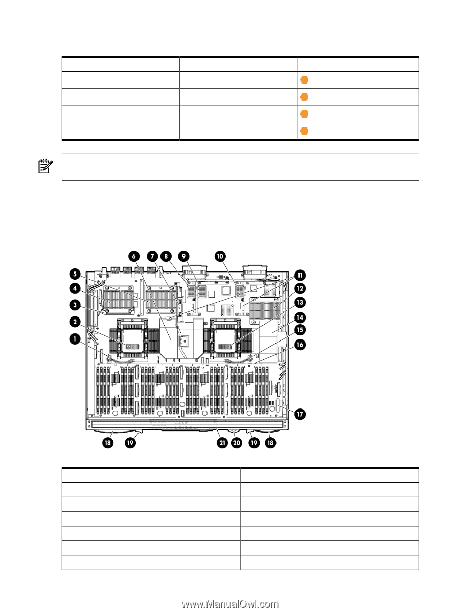
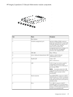
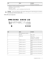
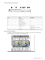
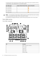
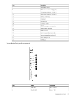
To support network connections for specific signals, install an interconnect module in the bay corresponding to the embedded NIC or mezzanine signals. Server blade signal NIC 1 (Embedded) NIC 2 (Embedded) NIC 3 (Embedded) NIC 4 (Embedded) Compute enclosure interconnect bay Interconnect bay labels 1 2 1 2 NOTE: For information on the location of LEDs and ports on individual interconnect modules, see the documentation that ships with the interconnect module. For detailed port mapping information, see the HP Integrity Superdome 2 User Service Guide. Server blade overview Server blade components Item 1 2 3 4 5 6 22 HP Integrity Superdome 2 system overview Description CPU 1 socket power connector CPU 1 socket Agent baffle Agent ASIC 1 Agent ASIC 0 Center air baffle
-
 1
1 -
2
-
3
-
4
-
5
-
6
-
7
-
8
-
9
-
10
-
11
-
12
-
13
-
14
-
15
-
16
-
 17
17 -
 18
18 -
 19
19 -
 20
20 -
 21
21 -
 22
22 -
 23
23 -
 24
24 -
 25
25 -
 26
26 -
 27
27 -
28
-
29
-
30
-
31
-
32
-
33
-
34
-
35
-
36
-
37
-
38
-
39
-
40
-
41
-
42
-
43
-
44
-
45
-
46
 |
 |