HP Integrity rx1600 Installation Guide, Second Edition - HP Integrity rx1600 - Page 57
Management Processor (MP) Card Event Logs, Identifying and Diagnosing Hardware Problems
 |
View all HP Integrity rx1600 manuals
Add to My Manuals
Save this manual to your list of manuals |
Page 57 highlights
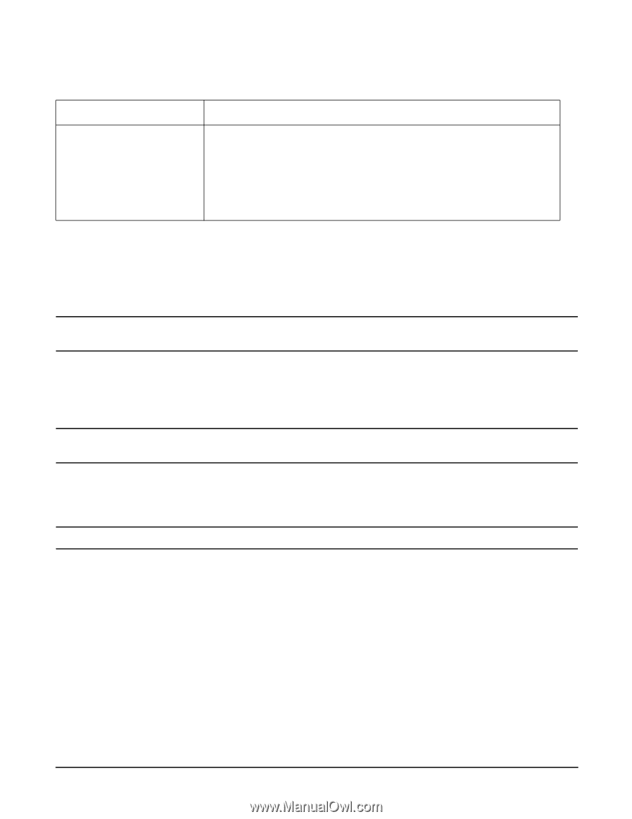
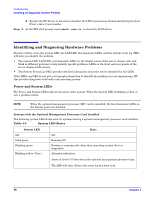
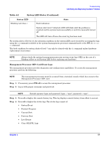
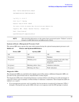
Troubleshooting Identifying and Diagnosing Hardware Problems Table 4-2 System LED States (Continued) System LED Blinking red (2/sec.) Fault indication: State System alert level 7 detected, LED will blink until the problem is resolved and the system boots successfully or until it is manually turned off. The LED will turn off once the event log has been read. For system alerts of levels 3-5, the attention condition on the system LED can be cleared by accessing the logs using the sl command available in the optional management processor command mode or the EFI cli cli>sl e command. The fault condition for system alerts of level 7 can only be cleared with the dc command unless hardware replacement is necessary. NOTE Always check the optional management processor system event logs (SEL) in the case of a blinking yellow or red System LED before replacing any hardware. Management Processor (MP) Card Event Logs The management processor provides diagnostic and configuration capabilities. To access the management processor, perform the following: NOTE The management processor must be accessed from a terminal console which has access to the Management Processor (MP) card. Step 1. If necessary, press CTRL+B to access the management processor. Step 2. Log in with proper username and password. NOTE Default operator login and password: login = "oper", password = "oper". Step 3. Press cl to display the console history log. This log displays console history from oldest to newest. Step 4. Press sl to display the status logs. The status logs consist of: • System Event • Forward Progress • Current Boot • Previous Boot • Live Events • Clear SEL/FPL Logs Chapter 4 57
-
 1
1 -
2
-
3
-
4
-
5
-
6
-
7
-
8
-
9
-
10
-
11
-
12
-
13
-
14
-
15
-
16
-
17
-
18
-
19
-
20
-
21
-
22
-
23
-
24
-
25
-
26
-
27
-
28
-
29
-
30
-
31
-
32
-
33
-
34
-
35
-
36
-
37
-
38
-
39
-
40
-
41
-
42
-
43
-
44
-
45
-
46
-
47
-
48
-
49
-
50
-
51
-
 52
52 -
 53
53 -
 54
54 -
 55
55 -
 56
56 -
 57
57 -
 58
58 -
 59
59 -
 60
60 -
 61
61 -
 62
62 -
63
-
64
-
65
-
66
-
67
-
68
-
69
-
70
-
71
-
72
-
73
-
74
-
75
-
76
-
77
-
78
-
79
-
80
-
81
-
82
-
83
-
84
-
85
-
86
-
87
-
88
-
89
-
90
 |
 |