HP Integrity rx7620 Installation Guide, Seventh Edition - HP Integrity rx7620
HP Integrity rx7620 Manual
 |
View all HP Integrity rx7620 manuals
Add to My Manuals
Save this manual to your list of manuals |
HP Integrity rx7620 manual content summary:
- HP Integrity rx7620 | Installation Guide, Seventh Edition - HP Integrity rx7620 - Page 1
Installation Guide HP Integrity rx7620 Server Seventh Edition Manufacturing Part Number : A7027-96037 May 2007 Printed in the U.S.A. © Copyright 1979-2007 HP Development Company, L.P. - HP Integrity rx7620 | Installation Guide, Seventh Edition - HP Integrity rx7620 - Page 2
warranty. HP shall not be liable for technical or editorial errors or omissions contained herein. Revision History First Edition Initial release. September 2003. Second Edition Added supported PCI card list. Minor edits. November 2003. Third Edition Minor edits. Added DVD+RW install instructions - HP Integrity rx7620 | Installation Guide, Seventh Edition - HP Integrity rx7620 - Page 3
3 - HP Integrity rx7620 | Installation Guide, Seventh Edition - HP Integrity rx7620 - Page 4
4 - HP Integrity rx7620 | Installation Guide, Seventh Edition - HP Integrity rx7620 - Page 5
Overview 12 System Backplane 13 I/O Subsystem 14 Detailed HP Integrity rx7620 Server Description 17 Cell Board 18 Cells and nPartitions 23 Internal Disk Devices for HP Integrity rx7620 Server 24 MP/SCSI Core I/O Board 24 Procurium LAN/SCSI Board 24 Mass Storage (Disk) Backplane 25 Server - HP Integrity rx7620 | Installation Guide, Seventh Edition - HP Integrity rx7620 - Page 6
Other Console Types 87 Additional Notes on Console Selection 87 Booting the HP Integrity rx7620 Server 88 Selecting a Boot Partition using the Management Processor 88 Verifying the System Configuration using the EFI shell 89 Booting HP-UX Using the EFI Shell 89 Using the Checklist 90 Index - HP Integrity rx7620 | Installation Guide, Seventh Edition - HP Integrity rx7620 - Page 7
16 Table 1-2. Cell Board CPU Load Order 20 Table 1-3. HP Integrity rx7620 Server DIMMs 21 Table 1-4. DIMM Load Order 22 Table 3-1. Wheel Kit Packing List 46 Table 3-2. Caster Part Numbers 50 Table 3-3. HP Integrity rx7620 Server - HP-UX Supported I/O Cards 54 Table 3-4. HP Integrity rx7620 - HP Integrity rx7620 | Installation Guide, Seventh Edition - HP Integrity rx7620 - Page 8
Tables 8 - HP Integrity rx7620 | Installation Guide, Seventh Edition - HP Integrity rx7620 - Page 9
System Backplane Block Diagram 14 Figure 1-4. PCI-X Board to Cell Board Block Diagram 15 Figure 1-5. HP Integrity rx7620 Server 8-Socket Block Diagram 17 Figure 1-6. Cell Board 18 Figure 1-7. Memory Subsystem 19 Figure 1-8. CPU Locations on Cell Board 20 Figure 1-9. DIMM Slot Layout 22 Figure - HP Integrity rx7620 | Installation Guide, Seventh Edition - HP Integrity rx7620 - Page 10
Figures Figure 4-8. MP Main Menu 81 Figure 4-9. The lc Command Screen 82 Figure 4-10. The ls Command Screen 83 Figure 4-11. Example sa Command 84 Figure 4-12. Browser Window 84 Figure 4-13. The du Command Screen 85 Figure 4-14. Console Output Device menu 86 10 - HP Integrity rx7620 | Installation Guide, Seventh Edition - HP Integrity rx7620 - Page 11
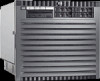
rp7410 product in the IA-64 product line. The HP Integrity rx7620 Server shares the same hardware as the HP 9000 rp7410 with changes to the cell board, CPU modules, core I/O and the PCI-X backplane. The HP Integrity rx7620 Server provides increased performance over its predecessor. Chapter 1 11 - HP Integrity rx7620 | Installation Guide, Seventh Edition - HP Integrity rx7620 - Page 12
Introduction Overview Overview The HP Integrity rx7620 Server is a 10U, 8-socket Symmetric Multi-Processing, rack-mount server that accommodates up to 64 GB of memory, PCI-X I/O, and internal peripherals, including disks and DVD/tape. Its high availability features include N+1 hot-pluggable fans - HP Integrity rx7620 | Installation Guide, Seventh Edition - HP Integrity rx7620 - Page 13
Figure 1-2 HP Integrity rx7620 Server (without front bezel) Introduction Overview System Backplane The system backplane comprises the system clock generation logic, the on the system backplane. The "crossbar-less" back-to-back CC connection increases performance and reduces costs. Chapter 1 13 - HP Integrity rx7620 | Installation Guide, Seventh Edition - HP Integrity rx7620 - Page 14
Introduction Overview Only half of the MP/SCSI reset and clock circuitry that propagates through the whole system. The central clocks drive all major chip set clocks. Therefore, these circuits represent a system wide single speed point to point data bus. The SBA can support up to 16 14 Chapter 1 - HP Integrity rx7620 | Installation Guide, Seventh Edition - HP Integrity rx7620 - Page 15
Overview of these high-speed bi-directional rope links for a total aggregate bandwidth of approximately 4 GB/sec. Each LBA acts as a bus bridge, supporting either one or two ropes and capable of driving 33 Mhz or 66 Mhz for PCI cards. The LBAs can also drive for HP Integrity rx7620 Server systems. - HP Integrity rx7620 | Installation Guide, Seventh Edition - HP Integrity rx7620 - Page 16
Introduction Overview Table 1-1 PCI-X Slot Types I/O Partition Slot Devicea 0 8 PCI (33 or 66 MHz) / PCI-X (66 or 133 slot is used as a PCI slot then either the 33MHz or 66MHz PCI frequency is supported. If the slot is used as a PCI-X slot then either the 66MHz or 133MHz PCI-X frequency is - HP Integrity rx7620 | Installation Guide, Seventh Edition - HP Integrity rx7620 - Page 17
Introduction Detailed HP Integrity rx7620 Server Description Detailed HP Integrity rx7620 Server Description Figure 1-5 HP Integrity rx7620 Server 8-Socket Block Diagram PDH Cell Board 0 Memory Cell Board 0 Memory CPU CPU CC CPU CPU CPU CPU CC CPU CPU CC Link PDH DVD/ Tape Bulk - HP Integrity rx7620 | Installation Guide, Seventh Edition - HP Integrity rx7620 - Page 18
Interface. The buses include two Front Side Buses (FBS0 and FBS1), a Memory (MID) bus, a Crossbar (XB) bus, and an I/O bus. All these blocks come together at the CC chip. Figure 1-6 Cell Board The HP Integrity rx7620 Server has a 48V distributed power system and receives the 48V power from the - HP Integrity rx7620 | Installation Guide, Seventh Edition - HP Integrity rx7620 - Page 19
Introduction Detailed HP Integrity rx7620 Server Description Figure 1-7 shows a simplified view of the memory subsystem. It consists of two independent access paths, each path having its own address bus, control bus, data bus, and DIMMs. In practice, the CC - HP Integrity rx7620 | Installation Guide, Seventh Edition - HP Integrity rx7620 - Page 20
1 Socket 0 DIMMs The memory DIMMs used by the HP Integrity rx7620 Server are custom-designed by HP and are identical to those used in the Superdome server. Each DIMM contains SDRAM memory components and is qualified to run at 125MHz. The CPU chip set will not support traditional DRAMs. 20 Chapter - HP Integrity rx7620 | Installation Guide, Seventh Edition - HP Integrity rx7620 - Page 21
be loaded in sets of four at specific locations. For best performance, HP recommends loading sets of eight DIMMs. Table 1-3 HP Integrity rx7620 Server DIMMs DIMM Size 256 MB 512 MB 1 GB 2 GB 4 GB Total Capacity 8 GB 16 GB 32 GB 64 GB 128 GB Memory Component Density 64 megabit 128 megabit 256 - HP Integrity rx7620 | Installation Guide, Seventh Edition - HP Integrity rx7620 - Page 22
Detailed HP Integrity rx7620 Server Description A quad seen in Figure 1-9 is a grouping of four DIMMs. Configurations with 8 or 16 Echelons 10 DIMMs = 5 Echelons 12 DIMMs = 6 Echelons 14 DIMMs = 7 Echelons 16 DIMMs = 8 Echelons Action Taken Install First Add Second Add Third Add Fourth Add Fifth - HP Integrity rx7620 | Installation Guide, Seventh Edition - HP Integrity rx7620 - Page 23
and sharing processes and memory space among the components. Each nPartition must have one root cell and may have both. The HP Integrity rx7620 Server has only two possible available on the Web at http://docs.hp.com Refer to HP System Partitions Guide: Administration for nPartitions for details. - HP Integrity rx7620 | Installation Guide, Seventh Edition - HP Integrity rx7620 - Page 24
HP Integrity rx7620 Server Description Internal Disk Devices for HP Integrity rx7620 Server In an HP Integrity rx7620 Server, the top internal disk drives connect to cell 1 through the core I/O for cell 1. Both of the bottom disk drives supported add-in PCI-X card. The Procurium board is hot - HP Integrity rx7620 | Installation Guide, Seventh Edition - HP Integrity rx7620 - Page 25
to disks are routed on the mass storage backplane, having connectors and termination circuitry. All disks are hot-pluggable. The HP Integrity rx7620 Server accommodates one internal removable media device. Therefore, only one power connector for a removable media device is required on the mass - HP Integrity rx7620 | Installation Guide, Seventh Edition - HP Integrity rx7620 - Page 26
Dimensions The dimensions of the HP Integrity rx7620 Server are as follows: • server units per 2 m rack and upgrade of current 10U height products in the future are the main height constraints. System Chassis The mass storage section located in the front allows access to the 3.5-inch hard drives - HP Integrity rx7620 | Installation Guide, Seventh Edition - HP Integrity rx7620 - Page 27
N+1 fully redundant BPSs. Figure 1-11 Right-Front View of HP Integrity rx7620 Server PCI-X cards Front panel display board PCI Power modules Cell removing the left side cover. The system backplane inserts by a guide/insertion mechanism using a single large jack screw assembly. SCSI ribbon- - HP Integrity rx7620 | Installation Guide, Seventh Edition - HP Integrity rx7620 - Page 28
Introduction Server Description Cell boards are accessed from the right side of the chassis behind a removable side cover. Figure 1-12 Left-Rear View of HP Integrity rx7620 Server System backplane MP/SCSI Core I/O Power Connectors 28 Chapter 1 - HP Integrity rx7620 | Installation Guide, Seventh Edition - HP Integrity rx7620 - Page 29
2 Unpacking the Server HP shipping containers are designed to protect their contents under normal shipping conditions. After the equipment arrives, carefully inspect each carton for signs of shipping damage. A - HP Integrity rx7620 | Installation Guide, Seventh Edition - HP Integrity rx7620 - Page 30
will indicate missing beads. If damage is found, document the damage with photographs and contact the transport carrier immediately. Examine the server cabinet for visible shipping damage. After unpacking the cabinet, check for damage that might have been obscured by the shipping container. If - HP Integrity rx7620 | Installation Guide, Seventh Edition - HP Integrity rx7620 - Page 31
Unpacking the Server Unpacking a Racked Server Unpacking a Racked Server This section contains information about unpacking the cabinet. WARNING Wear protective glasses while cutting the plastic bands around the shipping container. These bands are under - HP Integrity rx7620 | Installation Guide, Seventh Edition - HP Integrity rx7620 - Page 32
Unpacking the Server Unpacking a Racked Server CAUTION The plastic wrapping material should be cut off rather than pulled off. Pulling the plastic covering off represents an ESD hazard. Figure 2-1 Removing the Polystraps and Cardboard 32 Chapter 2 - HP Integrity rx7620 | Installation Guide, Seventh Edition - HP Integrity rx7620 - Page 33
Unpacking the Server Unpacking a Racked Server 5. Remove the four bolts that hold the ramps to the pallet, and remove the ramps. See Figure 2-2. Figure 2-2 Removing the Shipping Bolts and Plastic Cover Chapter 2 33 - HP Integrity rx7620 | Installation Guide, Seventh Edition - HP Integrity rx7620 - Page 34
the rack down the ramp and any time you roll the rack on the casters. Use caution when rolling the cabinet off the ramp. A single server in the cabinet weighs approximately 665 pounds. HP strongly recommends that two people roll the cabinet off the pallet. 34 Chapter 2 - HP Integrity rx7620 | Installation Guide, Seventh Edition - HP Integrity rx7620 - Page 35
Unpacking the Server Unpacking a Racked Server Securing the Cabinet When in position, secure and stabilize the cabinet, using the leveling feet at the corners of the base. Install the anti-tip mechanisms on the bottom front and rear of the rack. Figure 2-4 Securing the Cabinet Chapter 2 35 - HP Integrity rx7620 | Installation Guide, Seventh Edition - HP Integrity rx7620 - Page 36
. Because of the weight of the server, it must be centered on the lifter forks before raising it off the pallet to avoid injury. Never extend more than one server from the same cabinet while installing or servicing another server product. Failure to follow these instructions could result in the - HP Integrity rx7620 | Installation Guide, Seventh Edition - HP Integrity rx7620 - Page 37
Figure 2-5 RONI Lifter Unpacking the Server Unpacking a Non-Racked Server 1. Follow the instructions on the outside of the server packaging to remove the banding and carton top from the server pallet. Figure 2-6 Server with Shipping Box Removed 2. Remove all cartons from the pallet, leaving - HP Integrity rx7620 | Installation Guide, Seventh Edition - HP Integrity rx7620 - Page 38
access as shown in Figure 2-7. Figure 2-7 Remove Cushions for Lift Access Clearance for RonI lift is 28" x 5" Remove Cushions 4. Insert the lifter forks under the server. 5. Carefully roll the lift forward until it is fully positioned against the side of the - HP Integrity rx7620 | Installation Guide, Seventh Edition - HP Integrity rx7620 - Page 39
by two authorized HP service technicians. Before attempting this procedure, HP recommends that all cell boards and AC power supplies be removed. Instructions for removing these components can be found in the Removal and Replacement chapter of the service manual. Review local safety regulations - HP Integrity rx7620 | Installation Guide, Seventh Edition - HP Integrity rx7620 - Page 40
. Observe all ESD safety precautions before attempting this procedure. Failure to follow ESD safety precautions could result in damage to the server. 1. Remove both side covers. If present, remove the front panel. 2. Locate lift handles and remove from storage plate. 3. Orient lift handle - HP Integrity rx7620 | Installation Guide, Seventh Edition - HP Integrity rx7620 - Page 41
Unpacking the Server Unpacking a Non-Racked Server 4. With one handle in each hand, install the pin end of the panel into the back side of the front rack mount ears on the chassis. Figure 2-10 Inserting the Pins Into the Rack Chapter 2 41 - HP Integrity rx7620 | Installation Guide, Seventh Edition - HP Integrity rx7620 - Page 42
the system in a rack, refer to the Installation Guide, HP J1530B, Rack Installation Kit. 10. After moving the server, remove the lift handle panels from the chassis and reinstall the server covers and front bezel. Refer to the Installation Guide, HP J1530B Rack Installation Kit. 42 Chapter 2 - HP Integrity rx7620 | Installation Guide, Seventh Edition - HP Integrity rx7620 - Page 43
Unpacking the Server Installing Server Into the Rack Installing Server Into the Rack Any server that is to be installed into a rack is shipped with equipment slides. With every set of slides comes an installation guide: Installation Guide, HP J1530B, Rack Installation Kit. Chapter 2 43 - HP Integrity rx7620 | Installation Guide, Seventh Edition - HP Integrity rx7620 - Page 44
Unpacking the Server Installing Server Into the Rack 44 Chapter 2 - HP Integrity rx7620 | Installation Guide, Seventh Edition - HP Integrity rx7620 - Page 45
3 Installing Additional Components This chapter describes the installation of those components not installed at time of delivery. Chapter 3 45 - HP Integrity rx7620 | Installation Guide, Seventh Edition - HP Integrity rx7620 - Page 46
attach the ramp to the pallet) Tools Required for Installation The following list provides the installer with the recommended tools to perform the wheel kit installation. • Diagonal side cutters • Safety glasses • Torx screwdriver with T-15 bit • Phillips head screwdriver WARNING Wear protective - HP Integrity rx7620 | Installation Guide, Seventh Edition - HP Integrity rx7620 - Page 47
Installing Additional Components Wheel Kit Installation 1. Cut and remove the polystrap bands securing the HP server to the pallet. 2. Lift the carton top from the cardboard tray resting on the pallet. 3. Remove the bezel kit carton and the top cushions from - HP Integrity rx7620 | Installation Guide, Seventh Edition - HP Integrity rx7620 - Page 48
Components Wheel Kit Installation 4. Unfold bottom cardboard tray. 5. Carefully tilt the server and place one of the foam blocks (A6093-44002) under the left side of the server. Do not remove any other cushions until instructed to do so. Figure 3-2 Left Foam Block Position Foam Block Cardboard Tray - HP Integrity rx7620 | Installation Guide, Seventh Edition - HP Integrity rx7620 - Page 49
Installing Additional Components Wheel Kit Installation 6. Carefully tilt the server and place the other foam block provided in the kit under the right side of the server. Figure 3-3 Right Foam Block Position Foam Block MWK003 3/11/03 Chapter 3 49 - HP Integrity rx7620 | Installation Guide, Seventh Edition - HP Integrity rx7620 - Page 50
Installing Additional Components Wheel Kit Installation 7. Remove the cushions from the lower front and rear of the server. Do not disturb the side cushions. Figure 3-4 Foam Block Removal MWK004 3/12/03 8. Locate and identify the caster assemblies. Use the following table to identify - HP Integrity rx7620 | Installation Guide, Seventh Edition - HP Integrity rx7620 - Page 51
Locate and remove one of the four screws from the plastic pouch. Attach the a caster to the server. Figure 3-5 Attaching a Caster to the Server MWK005 3/12/03 10. Attach the remaining casters to the server using the screws supplied in the plastic pouch. 11. Remove the foam blocks from the left and - HP Integrity rx7620 | Installation Guide, Seventh Edition - HP Integrity rx7620 - Page 52
to fit on either side of the server. 16. Insert the slot on the caster cover into the front caster. Secure the cover to the server by tightening the captive screw on the cover at the rear of the server. Figure 3-6 Securing Each Caster Cover to the Server Rear Casters Caster Cover Front Casters - HP Integrity rx7620 | Installation Guide, Seventh Edition - HP Integrity rx7620 - Page 53
Figure 3-7 Completed Server Installing Additional Components Wheel Kit Installation Chapter 3 53 - HP Integrity rx7620 | Installation Guide, Seventh Edition - HP Integrity rx7620 - Page 54
supported in the HP Integrity rx7620 Server. Known cards supported at the release of this manual are shown in Tables 3-3 through 3-6. Table 3-3 HP Integrity rx7620 Server - HP-UX Supported 4 port 10/100Base-T 15 PCI 1 port 802.5 Token Ring 4/16/100 15 Obsidian USB/VGA PCI card 1 54 Chapter 3 - HP Integrity rx7620 | Installation Guide, Seventh Edition - HP Integrity rx7620 - Page 55
Installing Additional Components PCI-X Card Cage Assembly I/O Cards Table 3-3 HP Integrity rx7620 Server - HP-UX Supported I/O Cards (Continued) Part Number A6869B A7011A A7012A AB286A AB286C A3739B AB345A AB286C A3739B AB345A AB286C AB379A A5838A A9782A A9784A AB465A AB290A AD278A AD279A A5513A - HP Integrity rx7620 | Installation Guide, Seventh Edition - HP Integrity rx7620 - Page 56
(Continued) Part Number Card Description A6386A Z7340A Hyperfabric2 Fiber Adapter 8-port PCI ACC Number of Cards Supported (B-Bootable) 4 16 Table 3-4 HP Integrity rx7620 Server - Windows I/O Cards Part Number A7059A A7060A A7173A 337972-B21 A9890A A9891A AB287A AB232A AB466A AB467A AD167A - HP Integrity rx7620 | Installation Guide, Seventh Edition - HP Integrity rx7620 - Page 57
PCI 2-port 1000Base-T 8 AD144A PCI 1-port 10GbE SR (133Mhz) 2 AD145A PCI 4-port 1000Base-T 4 a. Not supported with AD145A 10 GbE adapter Table 3-6 HP Integrity rx7620 Server - Open VMS Supported I/O Cards Part Number A6826A A7173A AB378A AB379A AB545A Card Description Number of Cards - HP Integrity rx7620 | Installation Guide, Seventh Edition - HP Integrity rx7620 - Page 58
2 Gb FC/2 port 1 Gb Ethernet PCI X 2 port 1000Base T/2 port Ultra320 SCSI Number of Cards Supported (B-Bootable) 8 8 8 8 4B 4B 2B 2B PCI I/O Card Installation HP Integrity rx7620 Servers implement manual release latch (MRL) hardware for use in online add or replacement (OLAR) operations. If an MRL - HP Integrity rx7620 | Installation Guide, Seventh Edition - HP Integrity rx7620 - Page 59
steady OFF or is blinking if a user has requested the slot location. • copy of the interface card guide for instructions on preparing the operating system server. This procedure describes how to perform an online addition of a PCI card using the attention button for cards whose drivers support - HP Integrity rx7620 | Installation Guide, Seventh Edition - HP Integrity rx7620 - Page 60
resources from being impacted. For finer control over CRA actions use pdweb or the olrad command. Refer to the Interface Card OL* Support Guide located on the Web at http://docs.hp.com for details. Step 9. Replace the top cover. Step 10. Connect all cables to the installed PCI card. 60 Chapter 3 - HP Integrity rx7620 | Installation Guide, Seventh Edition - HP Integrity rx7620 - Page 61
to the server. Figure 3-9 Removable Media Bay Location Step 1. Remove the front bezel and top cover. and in the Remove and Replace Procedures. Step 2. Remove the drive bay blank or removable media drive. Step 3. Verify that the SCSI and power cables have the appropriate service length required - HP Integrity rx7620 | Installation Guide, Seventh Edition - HP Integrity rx7620 - Page 62
Installing Additional Components DVD+RW Installation Instructions IMPORTANT For the DVD+RW installation, the SCSI cable length must equal 1.5 inches, +/- 0.25 in. The power cable length must equal 3.5 inches, +/- 0.25 in. Figure 3-10 SCSI cable length 1.5" +/- 0.25" 62 Chapter 3 - HP Integrity rx7620 | Installation Guide, Seventh Edition - HP Integrity rx7620 - Page 63
Figure 3-11 Power cable length Installing Additional Components DVD+RW Installation Instructions 3.5" +/- 0.25" Step 4. Disconnect the three SCSI cables from the Mass Storage Backplane (MSBP). Drape the disconnected cables over to the side of the chassis. If - HP Integrity rx7620 | Installation Guide, Seventh Edition - HP Integrity rx7620 - Page 64
Installation Instructions Step Adjust the length of the SCSI and power cables to the appropriate service length described in Step 3. Step 9. Pull any excess cable length Step 12. Remove the DVD+RW drive from package. Step 13. Install the side rails onto the drive. Step 14. Connect the removable - HP Integrity rx7620 | Installation Guide, Seventh Edition - HP Integrity rx7620 - Page 65
. Step 19. Power on the server. Step 20. Boot the operating system. See "Powering On the System" in the Remove and Replace Procedures. Step 21. Install the appropriate device drivers. Use the installation instructions that come packaged with the drive to install device drivers. Chapter 3 65 - HP Integrity rx7620 | Installation Guide, Seventh Edition - HP Integrity rx7620 - Page 66
Installing Additional Components DVD+RW Installation Instructions 66 Chapter 3 - HP Integrity rx7620 | Installation Guide, Seventh Edition - HP Integrity rx7620 - Page 67
4 Cable Connections This chapter describes cable connections within the server. Chapter 4 67 - HP Integrity rx7620 | Installation Guide, Seventh Edition - HP Integrity rx7620 - Page 68
Cable Connections AC Input Power AC Input Power The server has five line cord configurations: • All four line cords (preferred configuration) • Cords A0 and A1 only • Cords B0 and B1 only • Cords A0 and B0 - HP Integrity rx7620 | Installation Guide, Seventh Edition - HP Integrity rx7620 - Page 69
is present even when the main power switch is in the off position. To completely remove power, all power cords must be removed from the server. Failure to observe this warning could result in personal injury or damage to equipment. NOTE System firmware will prevent boot when a single power cord - HP Integrity rx7620 | Installation Guide, Seventh Edition - HP Integrity rx7620 - Page 70
DC Input Power DC Input Power The HP Integrity rx7620 Server has two fast hot-pluggable DC bulk pwrgrd command is invoked, the following menu is displayed. IMPORTANT Options 1 and 2 are for HP internal use only. Do not select these options. prompt> pwrgrd Power grid configuration preference. 1. - HP Integrity rx7620 | Installation Guide, Seventh Edition - HP Integrity rx7620 - Page 71
Below is an illustration of the input power wiring. Figure 4-3 HP Integrity rx7620 Server - DC Power Input Cable Connections DC Input Power WARNING Voltage is present at various locations within the server whenever a power source is connected. This voltage is present even when the main power - HP Integrity rx7620 | Installation Guide, Seventh Edition - HP Integrity rx7620 - Page 72
type plug. This end plugs directly into the back of the HP Integrity rx7620 Server chassis. NOTE These procedures must be performed for each power cord that will be plugged directly into the back of the HP Integrity rx7620 Server. If the expected results from this procedure are not observed during - HP Integrity rx7620 | Installation Guide, Seventh Edition - HP Integrity rx7620 - Page 73
the following measurements. Figure 4-4 Voltage Reference Points for IEC 320 C19 Plug IMPORTANT These measurements must be performed for every power cord that plugs into the HP Integrity rx7620 Server. Step 1. Measure the voltage between L1 and L2. This is considered to be a phase-to-phase - HP Integrity rx7620 | Installation Guide, Seventh Edition - HP Integrity rx7620 - Page 74
between ground pins of the two power cords. Refer to Figure 4-5 for ground reference points when performing this measurement. Figure 4-5 Safety Ground Reference Check Step 1. Measure the voltage between B0 and not attempt to plug the power cords into the HP Integrity rx7620 Server. 74 Chapter 4 - HP Integrity rx7620 | Installation Guide, Seventh Edition - HP Integrity rx7620 - Page 75
is used, refer to applicable UPS documentation for information to connect the server and to check the UPS output voltage. UPS User Manual documentation is shipped with the UPS. Documentation may also be found at http://www.hp.com/racksolutions Step 1. Verify that site power is OFF. Step 2. Open the - HP Integrity rx7620 | Installation Guide, Seventh Edition - HP Integrity rx7620 - Page 76
or damage to equipment when AC power is applied to the cabinet. Step 9. Set the site power circuit breaker to ON. Step 10. Set the server power to ON. Step 11. Check that the indicator light on each power supply is lit. 76 Chapter 4 - HP Integrity rx7620 | Installation Guide, Seventh Edition - HP Integrity rx7620 - Page 77
MP Core I/O Connections MP Core I/O Connections Each HP Integrity rx7620 Server can have up to two MP Core I/O board SCSI board. The MP/SCSI board is oriented vertically and accessed from the back of the server. The LAN/SCSI is accessed from the PCI expansion card bay. Only the primary MP core - HP Integrity rx7620 | Installation Guide, Seventh Edition - HP Integrity rx7620 - Page 78
(PC) The Customer Engineer (CE) Tool is usually a laptop. It allows communication with the Management Processor (MP) in the HP Integrity rx7620 Server. The MP monitors the activity of either a one partition or a multiple-partition configuration. During installation, communicating with the MP enables - HP Integrity rx7620 | Installation Guide, Seventh Edition - HP Integrity rx7620 - Page 79
The power switch is a DC power switch that controls +48V DC. Before powering up the HP Integrity rx7620 Server for the first time: 1. Verify that the AC voltage at the input source is within specifications for each server being installed. 2. If not already done so, power on the serial display device - HP Integrity rx7620 | Installation Guide, Seventh Edition - HP Integrity rx7620 - Page 80
Cable Connections MP Core I/O Connections On the front of the HP Integrity rx7620 Server, a solid green Standby Power LED, a solid green MP Present LED, and a flashing amber Attention LED will illuminate after about 30 seconds. Figure 4-7 Front Panel Display 2. - HP Integrity rx7620 | Installation Guide, Seventh Edition - HP Integrity rx7620 - Page 81
if default values are to be modified, is displayed. It is a good idea to write down the information, because it might be required for future troubleshooting. NOTE If the Command Menu is not shown, enter q to return to the MP Main Menu, then enter cm.. Chapter 4 81 - HP Integrity rx7620 | Installation Guide, Seventh Edition - HP Integrity rx7620 - Page 82
the customer LAN. The name can be as many as 64 characters in length, and include alphanumeric characters, - (dash), _ (under bar),. (period), or a space. HP recommends that the name be a derivative of the complex name. For example, Acme.com_MP. 7. Enter the LAN parameters for the Subnet mask and - HP Integrity rx7620 | Installation Guide, Seventh Edition - HP Integrity rx7620 - Page 83
MP. The Web browser allows access to the server through the LAN port on the core I/O networking information from that of the port used by HP-UX. Before starting this procedure, the following information configure the LAN port for a Web browser, perform the following steps: Step 1. Connect to the MP - HP Integrity rx7620 | Installation Guide, Seventh Edition - HP Integrity rx7620 - Page 84
Cable Connections MP Core I/O Connections Step 4. Type SA at the MP:CM> prompt to display and set MP remote access. Figure 4-11 Example sa Command Step 5. Launch a Web browser on the same subnet using the IP address for the MP LAN port. Figure 4-12 Browser Window Zoom In/Out Title Bar Step 6. Click - HP Integrity rx7620 | Installation Guide, Seventh Edition - HP Integrity rx7620 - Page 85
to the MP when the login window appears. Access to the MP via a Web browser is now possible. Verifying Presence of the Cell Boards To perform this activity, either connect to the Management Processor (MP) using a console, or connect the CE Tool (laptop) to the RS-232 Local port on the - HP Integrity rx7620 | Installation Guide, Seventh Edition - HP Integrity rx7620 - Page 86
Cable Connections System Console Selection System Console Selection Each operating system requires that the correct console type be selected from the firmware selection menu. The following section describes how to determine the correct console device. If an operating system is being installed or the - HP Integrity rx7620 | Installation Guide, Seventh Edition - HP Integrity rx7620 - Page 87
that matches your console type(PcAnsi, Vt100, Vt100+, VtUtf8) and deselect everything else. If you choose either a system or MP serial port HP recommends that you use a vt100+ capable terminal device. Additional Notes on Console Selection Each Operating System makes decisions based on the EFI Boot - HP Integrity rx7620 | Installation Guide, Seventh Edition - HP Integrity rx7620 - Page 88
Cable Connections Booting the HP Integrity rx7620 Server Booting the HP Integrity rx7620 Server After powering on the Management Processor (MP), +3.3 V Housekeeping power, and verifying that the MP detects the presence of the cell boards, power up the server. If using a LAN crossover cable with the - HP Integrity rx7620 | Installation Guide, Seventh Edition - HP Integrity rx7620 - Page 89
Cable Connections Booting the HP Integrity rx7620 Server 1. From the MP Main Menu, enter cm. 2. From the to the configuration menu, where system configuration can be reset, configured or viewed. • memory -- memory related commands. Once the parameters have been verified, enter x to return to the EFI - HP Integrity rx7620 | Installation Guide, Seventh Edition - HP Integrity rx7620 - Page 90
procedures described in the body of this manual. This checklist is a compilation of the tasks described in this manual, and is organized as follows: PROCEDURES type, sub tasks are indented. Table 4-2 Factory-Integrated Installation Checklist PROCEDURE Initials Obtain LAN information Verify site - HP Integrity rx7620 | Installation Guide, Seventh Edition - HP Integrity rx7620 - Page 91
Cable Connections Using the Checklist Table 4-2 Factory-Integrated Installation Checklist (Continued) (Continued) PROCEDURE Unpack other equipment Remove See Appendix B. Verify remote link (if required) Install non-factory, integrated I/O cards (if required) IN-PROCESS COMPLETED Chapter 4 91 - HP Integrity rx7620 | Installation Guide, Seventh Edition - HP Integrity rx7620 - Page 92
Factory-Integrated Installation Checklist (Continued) (Continued) PROCEDURE Select PCI card slot Install PCI card Verify installation Route cables using the cable management arm Install other peripherals (if required) Perform visual inspection and complete installation Set up network services (if - HP Integrity rx7620 | Installation Guide, Seventh Edition - HP Integrity rx7620 - Page 93
MP bus topology), 85 lc (LAN configuration), 82 ls (LAN status), 82 vfp (Virtual Front Panel), 88 D di (Display) command, 88 DIMMs, 19 memory, 19 disk internal, 25, 77 du (display MP bus topology) command, 85 F front panel display, 80 G gateway address, 82 H housekeeping power, 79 I installation - HP Integrity rx7620 | Installation Guide, Seventh Edition - HP Integrity rx7620 - Page 94
Index V verifying system configuration, 88 voltage check, 75 94
-
 1
1 -
 2
2 -
 3
3 -
 4
4 -
 5
5 -
 6
6 -
 7
7 -
8
-
9
-
10
-
11
-
12
-
13
-
14
-
15
-
16
-
17
-
18
-
19
-
20
-
21
-
22
-
23
-
24
-
25
-
26
-
27
-
28
-
29
-
30
-
31
-
32
-
33
-
34
-
35
-
36
-
37
-
38
-
39
-
40
-
41
-
42
-
43
-
44
-
45
-
46
-
47
-
48
-
49
-
50
-
51
-
52
-
53
-
54
-
55
-
56
-
57
-
58
-
59
-
60
-
61
-
62
-
63
-
64
-
65
-
66
-
67
-
68
-
69
-
70
-
71
-
72
-
73
-
74
-
75
-
76
-
77
-
78
-
79
-
80
-
81
-
82
-
83
-
84
-
85
-
86
-
87
-
88
-
89
-
90
-
91
-
92
-
93
-
94
 |
 |

Installation Guide
HP Integrity rx7620 Server
Seventh Edition
Manufacturing Part Number : A7027-96037
May 2007
Printed in the U.S.A.
© Copyright 1979-2007 HP Development Company, L.P.