HP Integrity rx8640 Site Preparation Guide, Fourth Edition - HP Integrity rx86 - Page 21
Valid Memory Configurations
 |
View all HP Integrity rx8640 manuals
Add to My Manuals
Save this manual to your list of manuals |
Page 21 highlights
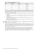
Valid Memory Configurations The first cell must have one DIMM pair loaded in slots 0A/0B. The server can support as little as 2 GB of main memory using two 1 GB DIMMs installed on one of the cell boards and as much as 512 GB by filling all 16 DIMM slots on all four cell boards with 8 GB DIMMs. The following rules explain the memory configuration: 1. DIMMs must be loaded in pairs (same size within a pair). 2. DIMM pairs must be loaded in slot order (0A/0B, 1A/1B, 2A/2B, ...) 3. Largest DIMMs must be loaded first followed by progressively smaller DIMM module sizes. A paired set of DIMMs is called a rank. DIMMs in a rank must be of the same capacity. See Table 1-3 and Figure 1-9for DIMM load order and layout on the cell board. A quad is a grouping of four DIMMs (Figure 1-9). Configurations with 8 or 16 DIMM slots loaded are recommended. Adding a rank enables a dedicated DDR-II bus on a cell to increase the amount of usable memory bandwidth available. Available memory is proportional to the amount of memory installed. Table 1-3 DIMM Load Order Number of DIMMs Installed 2 DIMMs = 1 rank 4 DIMMs = 2 rank 6 DIMMs = 3 rank 8 DIMMs = 4 rank 10 DIMMs = 5 rank 12 DIMMs = 6 rank 14 DIMMs = 7 rank 16 DIMMs = 8 rank Action Taken Install first Add second Add third Add fourth Add fifth Add sixth Add seventh Add last DIMM Location on Cell Quad Location Board 0A and 0B Quad 2 1A and 1B Quad 1 2A and 2B Quad 3 3A and 3B Quad 0 4A and 4B Quad 2 5A and 5B Quad 1 6A and 6B Quad 3 7A and 7B Quad 0 Figure 1-9 DIMM Slot Layout 6A Front Edge of Cell Board 1A 6B 1B 2B 2A Quad 3 5B Quad 1 5A 0A Quad 2 Quad 0 7A 0B 7B 3B 4B 3A 4A Rear Edge of Cell Board (Plugs into Server Backplane) Detailed Server Description 21
-
 1
1 -
2
-
3
-
4
-
5
-
6
-
7
-
8
-
9
-
10
-
11
-
12
-
13
-
14
-
15
-
 16
16 -
 17
17 -
 18
18 -
 19
19 -
 20
20 -
 21
21 -
 22
22 -
 23
23 -
 24
24 -
 25
25 -
 26
26 -
27
-
28
-
29
-
30
-
31
-
32
-
33
-
34
-
35
-
36
-
37
-
38
-
39
-
40
-
41
-
42
-
43
-
44
-
45
 |
 |
