HP Integrity rx8640 Site Preparation Guide, Fourth Edition - HP Integrity rx86 - Page 23
System Backplane
 |
View all HP Integrity rx8640 manuals
Add to My Manuals
Save this manual to your list of manuals |
Page 23 highlights
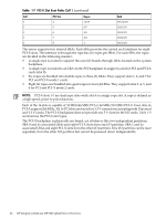
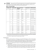
Table 1-4 Removable Media Drive Path Removable Media Slot 0 media Path 0/0/0/2/1.x1.0 Slot 1 media 1/0/0/2/1.x1.0 1 X equals 2 for a DVD drive while X equals 3 for a DDS-4 DAT drive. Table 1-5 Hard Disk Drive Path Hard Drive Slot 0 drive Slot 1 drive Slot 2 drive Slot 3 drive Path 0/0/0/2/0.6.0 0/0/0/3/0.6.0 1/0/0/2/0.6.0 1/0/0/3/0.6.0 System Backplane The system backplane board contains the following components: • Two crossbar chips (XBC) • Clock generation logic • Preset generation logic • Power regulators • Two local bus adapter (LBA) chips that create internal PCI buses for communicating with the core I/O card. The backplane also contains connectors for attaching the cell boards, PCI-X backplane, MP core I/O cards SCSI cables, bulk power, chassis fans, front panel display, intrusion switches, and external system bus adapters (SBA) link connectors. Figure 1-11 System Backplane Block Diagram System Backplane LBA Core I/O 0 LBA PCI-X Backplane Cell 0 Cell 1 XBC XBC Cell boards are perpendicular to the system backplane. Cell 2 Core I/O 1 Cell 3 Detailed Server Description 23
-
 1
1 -
2
-
3
-
4
-
5
-
6
-
7
-
8
-
9
-
10
-
11
-
12
-
13
-
14
-
15
-
16
-
17
-
 18
18 -
 19
19 -
 20
20 -
 21
21 -
 22
22 -
 23
23 -
 24
24 -
 25
25 -
 26
26 -
 27
27 -
 28
28 -
29
-
30
-
31
-
32
-
33
-
34
-
35
-
36
-
37
-
38
-
39
-
40
-
41
-
42
-
43
-
44
-
45
 |
 |
