HP Integrity rx8640 Site Preparation Guide, Fourth Edition - HP Integrity rx86 - Page 25
PCI-X Board to CellBoard Block Diagram, Table 1-6 PCI-X Slot Boot Paths Cell 0
 |
View all HP Integrity rx8640 manuals
Add to My Manuals
Save this manual to your list of manuals |
Page 25 highlights
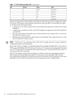
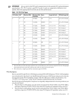
and at 266 MT/s for PCI-X mode 2 cards installed in mode 2 capable slots. When cell board 2 and cell board 3 are present, the cell boards attach to their own associated SBA and LBA chips on the PCI-X board in the Server Expansion Unit. Figure 1-12 PCI-X Board to Cell Board Block Diagram Table 1-6 and Table 1-7 list the mapping of PCI-X slots to boot paths. The cell column refers to the cell boards installed in the server. Table 1-6 PCI-X Slot Boot Paths Cell 0 Cell PCI Slot Ropes 0 1 8/9 0 2 10/11 0 3 12/13 0 4 14/15 0 5 6/7 0 6 4/5 0 7 2/3 0 8 1 Path 0/0/8/1/0 0/0/10/1/0 0/0/12/1/0 0/0/14/1/0 0/0/6/1/0 0/0/4/1/0 0/0/2/1/0 0/0/1/1/0 Table 1-7 PCI-X Slot Boot Paths Cell 1 Cell PCI Slot Ropes 1 1 8/9 1 2 10/11 1 3 12/13 Path 1/0/8/1/0 1/0/10/1/0 1/0/12/1/0 Detailed Server Description 25
-
 1
1 -
2
-
3
-
4
-
5
-
6
-
7
-
8
-
9
-
10
-
11
-
12
-
13
-
14
-
15
-
16
-
17
-
18
-
19
-
 20
20 -
 21
21 -
 22
22 -
 23
23 -
 24
24 -
 25
25 -
 26
26 -
 27
27 -
 28
28 -
 29
29 -
 30
30 -
31
-
32
-
33
-
34
-
35
-
36
-
37
-
38
-
39
-
40
-
41
-
42
-
43
-
44
-
45
 |
 |
