HP LH4r HP Netserver LH 4 Installation Road Map - Page 3
Preparation, Removing and Replacing the Covers, Install All Accessory Boards
 |
View all HP LH4r manuals
Add to My Manuals
Save this manual to your list of manuals |
Page 3 highlights
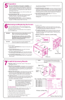
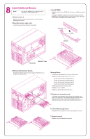
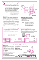
5Preparation 1. Boot the HP NetServer Navigator CD-ROM: Turn on the monitor. Press the power-on button on the HP NetServer, and press the eject button on the CD-ROM drive. Place the HP NetServer Navigator CD-ROM in the drive, and close the drive. Press the Reset button. If the system fails to restart, follow the instructions on the screen. When HP Navigator starts, you can set the time and date, and change the display language. 2. Read the Readme File: Select "Readme File" from the HP Navigator Main Menu. The Readme file contains the latest information to help you install your HP NetServer. 3. Run DiagTools (Optional): To verify the HP NetServer hardware as shipped, copy Diag Tools from the HP NetServer Navigator CD-ROM to diskette. Refer to the online documentation HP NetServer DiagTools Error Reference and User Guide for more information. 4. Install Information Assistant: Information Assistant will help you install your HP NetServer. It is easier to use from a stand-alone system, rather than from the HP NetServer you are installing. Install Information Assistant from the HP NetServer Online Documentation CD-ROM onto the client system that you will be using to manage your HP NetServer. 5. Visit Order Assistant (optional) on the Internet at http://www.hp.com/go/netserver Order Assistant lists HP accessories, cables, and connectors for your HP NetServer. 6Removing and Replacing the Covers If you are installing accessory cards or mass storage devices, remove the front bezel and cover 1. If you are installing memory, remove the front bezel and cover 3. To install some options, you will need a flat 1/4-inch screwdriver and a T15 TORX® driver. WARNING Before removing cover(s), always disconnect the power cord and unplug telephone cables. Note that the power switch does not turn off the standby power. Disconnect the power cord to turn off standby power. If the backlight on the LCD display is on, standby power is on. To replace a cover: 1. To replace a cover, insert the tabs inside the rear of the cover into the slots at rear of the chassis and slide the side cover toward the rear. Tighten the thumbscrew at the front of the cover. 2. To replace the bezel, insert the tabs at the bottom of the bezel into the slots at the bottom of the chassis front and press the top of the bezel to the chassis until it snaps into place. Lock the bezel lock with the key provided. 3. Replace all power, telephone, and I/O cables. Bezel Lock CAUTION Wear a wrist strap and use a static-dissipating work surface connected to the chassis at all times. To remove a cover: 1. Turn off the HP NetServer and disconnect the power cord and telephone cord. 2. Unlock the bezel lock with the key from the key bag located on the rear of the HP NetServer. 3. To remove the front bezel, pull the top of the bezel away from the chassis, and then lift the bezel up and off of the chassis. 4. Loosen the thumbscrew at the front of the cover and pull the cover forward, using the handle on the cover, and then lift it off the chassis. Cover 1 Unlocked Position Cover 2 Cover 3 Thumbscrews Front Bezel Tabs and Slots 7 Install All Accessory Boards 1. Remove cover 1 as described in panel 6: "Removing and Replacing the Covers." 2. Read the documentation included with each accessory board. Follow any special instructions and installation recommendations. Some boards have preferred slot locations. If not, consider the boot order (see below) when choosing the accessory board socket in which to install the board. 3. Remove the slot cover for each slot to be used, and store it for future use. If you are installing any full-length PCI boards, also remove the accessory board retainer. Push on the button on the retainer to release it, and then slide it out of the board guide. 4. Install the boards: Insert each board in the desired slot and fasten the board's mounting screw at the slot opening at the rear of the chassis. Connect any required cables to the boards. If you removed the board retainer, reinstall it. NOTE If you install an ISA non-Plug-and-Play board, you must reserve system resources (some or all of: memory addresses, I/O addresses, IRQs, and DMA channels) for it. Write down that information now for reference when you reserve system resouces in Panel 12: "Configure the HP NetServer." Boot Device Priority Boot order for PCI controllers is determined by slot location. The system searches for a bootable device in the following order: 1. IDE CD-ROM drive with a bootable CD-ROM. 2. Flexible disk drive with a bootable flexible disk. 3. Embedded SCSI controller or embedded DAC. 4. PCI boards in slots in the following order: 8, 7, 6, 5, 4, 3, 2, 1. This boot order can be changed using the SETUP utility (press [F2] during the boot process). NOTE For a list of boards HP has tested, see Help topic "Tested Parts List" on the HP Navigator CD-ROM. Accessory Board Guide Release Tab Accessory Board Retainer Slot 1 16-bit ISA or 32-bit PCI Slot 2 32-bit PCI Slot 3 32-bit PCI Slot 4 32-bit PCI Slot 5 32-bit PCI Slot 6 32-bit PCI Slot 7 64-bit PCI Slot 8 64-bit PCI PCI Board- Left-Side Offset ISA Board- Right-Side Offset
-
 1
1 -
 2
2 -
 3
3 -
 4
4 -
 5
5 -
 6
6
 |
 |
