HP LH4r HP Netserver LH 4 Installation Road Map - Page 4
Install Additional Memory
 |
View all HP LH4r manuals
Add to My Manuals
Save this manual to your list of manuals |
Page 4 highlights
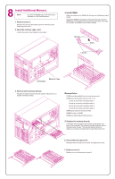
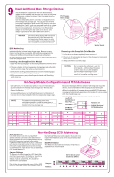
8 Install Additional Memory NOTE Use only HP DIMMs listed in HP Information Assistant or in HP Order Assistant. 1. Remove cover 2. Remove the cover as described in panel 6, "Removing and Replacing the Covers." 2. Open the memory cage cover. Loosen the cover screw. Swing the cover open. 4. Install DIMMs. Align the notches on the DIMM with the keys on the Memory board socket. Holding the DIMM at 90 degrees to the system board, press the DIMM fully into the socket until the retaining clips close. If the clips do not close, the DIMM is not inserted correctly. Notches Keys Latches Hard Disks Memory Cage 3. Remove both memory boards. Release the latches and remove both boards. Place them on a suitable anti-static surface. Memory Rules: DIMMs must be installed four at a time, two per card. DIMMs must be installed in banks, from 1 to 4. J1 and J2 of memory A and B are bank 1. J3 and J4 of memory A and B are bank 2. J5 and J6 of memory A and B are bank 3. J7 and J8 of memory A and B are bank 4. DIMM types cannot be mixed per bank. DIMMS are 64 or 256 MB. DIMMs are EDO buffered TSOP at 50 ns. 5. Replace the memory boards. Insert each memory board, one at a time, into its guide, and press it into its socket. The retaining clips flip along the sides of the board when it seats. The memory boards need to be identical, so it does not matter which board is Memory A or B. 6. Close memory cage cover. Swing the memory cage cover closed, and tighten the screw. 7. Replace cover 2. Replace cover 2 as described in panel 6.
-
 1
1 -
 2
2 -
 3
3 -
 4
4 -
 5
5 -
 6
6
 |
 |
