HP LH4r HP Netserver LXr Pro8 - Page 10
slots. You might want to use this diagram to mark or highlight the slot or slots
 |
View all HP LH4r manuals
Add to My Manuals
Save this manual to your list of manuals |
Page 10 highlights
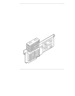
Chapter 2 Plan the Upgrade Table 2-1. Processor Board Configurations Total Number of CPU Chips in System 2 CPUs 4 CPUs 6 CPUs 8 CPUs Board in Slot A1 Processor board Processor board Processor board Processor board Board in Slot A2 Terminator board Terminator board Processor board Processor board Board in Slot B1 Terminator board Processor board Processor board Processor board Board in Slot B2 Terminator board Terminator board Terminator board Processor board Figure 2-1 shows a diagram of a system board which labels the processor board slots. You might want to use this diagram to mark or highlight the slot (or slots) on the system board where you will remove a terminator board to install a 200 MHz/1 MB processor board. Figure 2-1. System Board of HP NetServer LXr Pro8 6
-
 1
1 -
2
-
3
-
4
-
 5
5 -
 6
6 -
 7
7 -
 8
8 -
 9
9 -
 10
10 -
 11
11 -
 12
12 -
 13
13 -
 14
14 -
 15
15 -
16
-
17
-
18
-
19
-
20
-
21
-
22
-
23
-
24
-
25
-
26
-
27
 |
 |
