HP Latex 375 User Guide Latex 3x5 - Page 14
Main printer components
 |
View all HP Latex 375 manuals
Add to My Manuals
Save this manual to your list of manuals |
Page 14 highlights
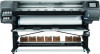
Label Explanation Electric shock hazard. The printer has two input power cords. Power supplies operate at hazardous voltages. Disconnect all power cords before servicing. This label is located internally (in the 365 and 375 only), close to the print-zone heating-coils enclosure between fans. For service personnel only. Hazardous moving parts. Rotating fan blades. Keep hands clear. These labels are located internally, close to the print-zone heating fans between fans (365 and 375 only), one near the vacuum fan and one near the aerosol fan. For service personnel only. Hazardous area. Heating modules operate at hazardous voltages. Electric shock hazard. Equipment has two input power cords. Disconnect all power cords before servicing. Power supplies operate at hazardous voltages. Double pole, neutral fusing. Equipment to be connected to earthed mains outlet only. This label is located in the scan and air-curtain heater control enclosure (365 and 375 only). For service personnel only. NOTE: The final label position and its size on the printer may vary slightly, but should always be visible and close to the potential risk area. Main printer components The above image is a QR code containing a link to a video; see Documentation on page 3. The following views of the printer illustrate its main components. 8 Chapter 1 Introduction ENWW
-
 1
1 -
2
-
3
-
4
-
5
-
6
-
7
-
8
-
 9
9 -
 10
10 -
 11
11 -
 12
12 -
 13
13 -
 14
14 -
 15
15 -
 16
16 -
 17
17 -
 18
18 -
 19
19 -
20
-
21
-
22
-
23
-
24
-
25
-
26
-
27
-
28
-
29
-
30
-
31
-
32
-
33
-
34
-
35
-
36
-
37
-
38
-
39
-
40
-
41
-
42
-
43
-
44
-
45
-
46
-
47
-
48
-
49
-
50
-
51
-
52
-
53
-
54
-
55
-
56
-
57
-
58
-
59
-
60
-
61
-
62
-
63
-
64
-
65
-
66
-
67
-
68
-
69
-
70
-
71
-
72
-
73
-
74
-
75
-
76
-
77
-
78
-
79
-
80
-
81
-
82
-
83
-
84
-
85
-
86
-
87
-
88
-
89
-
90
-
91
-
92
-
93
-
94
-
95
-
96
-
97
-
98
-
99
-
100
-
101
-
102
-
103
-
104
-
105
-
106
-
107
-
108
-
109
-
110
-
111
-
112
-
113
-
114
-
115
-
116
-
117
-
118
-
119
-
120
-
121
-
122
-
123
-
124
-
125
-
126
-
127
-
128
-
129
-
130
-
131
-
132
-
133
-
134
-
135
-
136
-
137
-
138
-
139
-
140
-
141
-
142
-
143
-
144
-
145
-
146
-
147
-
148
-
149
-
150
-
151
-
152
-
153
-
154
-
155
-
156
-
157
-
158
-
159
-
160
-
161
-
162
-
163
-
164
-
165
-
166
-
167
-
168
-
169
-
170
-
171
-
172
-
173
-
174
-
175
-
176
-
177
-
178
-
179
-
180
-
181
-
182
-
183
-
184
-
185
-
186
-
187
-
188
-
189
-
190
-
191
-
192
 |
 |
