HP ML150 HP Power Capping and Dynamic Power Capping for ProLiant servers techn - Page 10
Enclosure Dynamic Power Capping operation
 |
UPC - 884420743644
View all HP ML150 manuals
Add to My Manuals
Save this manual to your list of manuals |
Page 10 highlights
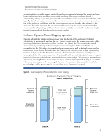
Cooling fans for the enclosure The enclosure's Onboard Administrator(s) An administrator can set the power cap for the enclosure to any value between the power cap lower bound and the maximum available power for the enclosure. The power cap lower bound is determined by adding up the total power that the server blades would use in their lowest P-state mode (typically about halfway between server idle and server maximum power), the maximum power that fans in the enclosure could draw, and the power-on power requests from the other elements in the enclosure. This value represents the lowest reasonable power cap that can be maintained for the enclosure under all operating conditions. The maximum available power for the enclosure is simply the total power available from the enclosure power supplies. Enclosure Dynamic Power Capping operation Once an administrator sets an enclosure power cap, it is the job of the enclosure's Onboard Administrator to monitor and maintain the cap. Since it cannot control the power consumption of the unmanaged elements in the enclosure (fans, switches, and others), the OA maintains the overall enclosure cap by monitoring and managing the power consumption of the server blades. To accomplish this, the OA collects the overall enclosure power use as well as the total power used by the managed server blades. From this data, the OA constructs a blade power budget, representing the amount of power that the blades can consume while keeping the enclosure's overall power consumption below the enclosure cap. As a final step, OA software actively adjusts the power caps of the individual servers so that the total matches the blade power budget. This process is repeated every 20 seconds, ensuring that the enclosure power cap is continuously maintained. As Figure 4 illustrates, if the power consumption of the unmanaged elements in the enclosure decreases, then the blade power budget and the power caps for the individual server blades are increased. Figure 4. Power budgeting in Enclosure Dynamic Power Capping Enclosure Dynamic Power Capping Power Budgeting Enclosure Dynamic Power Cap Power used by unmanaged elements Enclosure Dynamic Power Cap Power Cap Lower Bound Blade Power Budget Power Cap Lower Bound Time A Time B 10
-
 1
1 -
2
-
3
-
4
-
 5
5 -
 6
6 -
 7
7 -
 8
8 -
 9
9 -
 10
10 -
 11
11 -
 12
12 -
 13
13 -
 14
14 -
 15
15 -
16
-
17
-
18
-
19
-
20
-
21
-
22
-
23
-
24
-
25
-
26
 |
 |
