HP Mini 110-4100ca HP Mini 210, HP Mini 110, Compaq Mini CQ10 - Maintenance an - Page 83
until the jacks and ports on the right side of the, Flex the right side of the base enclosure
 |
View all HP Mini 110-4100ca manuals
Add to My Manuals
Save this manual to your list of manuals |
Page 83 highlights
● WWAN module (see WWAN module on page 55) ● RTC battery (see RTC battery on page 58) ● Memory module (see Memory module on page 57) ● Power connector cable (see System board on page 74) ● Fan (see Fan on page 77) ● Heat sink (see Heat sink on page 79) Remove the system board: 1. Remove the two Phillips PM2.0×5.7 screws that secure the system board to the base enclosure. 2. Release the power connector (1) from the clip built into the base enclosure. 3. Flex the right side of the base enclosure (2) until the jacks and ports on the right side of the system board are clear of the openings in the base enclosure. 4. Lift the right side of the system board (3) until it rests at an angle. Component replacement procedures 75
-
 1
1 -
2
-
3
-
4
-
5
-
6
-
7
-
8
-
9
-
10
-
11
-
12
-
13
-
14
-
15
-
16
-
17
-
18
-
19
-
20
-
21
-
22
-
23
-
24
-
25
-
26
-
27
-
28
-
29
-
30
-
31
-
32
-
33
-
34
-
35
-
36
-
37
-
38
-
39
-
40
-
41
-
42
-
43
-
44
-
45
-
46
-
47
-
48
-
49
-
50
-
51
-
52
-
53
-
54
-
55
-
56
-
57
-
58
-
59
-
60
-
61
-
62
-
63
-
64
-
65
-
66
-
67
-
68
-
69
-
70
-
71
-
72
-
73
-
74
-
75
-
76
-
77
-
 78
78 -
 79
79 -
 80
80 -
 81
81 -
 82
82 -
 83
83 -
 84
84 -
 85
85 -
 86
86 -
 87
87 -
 88
88 -
89
-
90
-
91
-
92
-
93
-
94
-
95
-
96
-
97
-
98
-
99
-
100
-
101
-
102
-
103
-
104
-
105
-
106
-
107
-
108
-
109
-
110
-
111
-
112
-
113
-
114
 |
 |

●
WWAN module (see
WWAN module
on page
55
)
●
RTC battery (see
RTC battery
on page
58
)
●
Memory module (see
Memory module
on page
57
)
●
Power connector cable (see
System board
on page
74
)
●
Fan (see
Fan
on page
77
)
●
Heat sink (see
Heat sink
on page
79
)
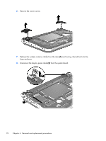
Remove the system board:
1.
Remove the two Phillips PM2.0×5.7 screws that secure the system board to the base enclosure.
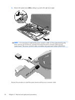
2.
Release the power connector
(1)
from the clip built into the base enclosure.
3.
Flex the right side of the base enclosure
(2)
until the jacks and ports on the right side of the
system board are clear of the openings in the base enclosure.
4.
Lift the right side of the system board
(3)
until it rests at an angle.
Component replacement procedures
75