HP Nx9600 Compaq Presario X6000 and HP Compaq nx9600 Notebook PC - Maintenance - Page 109
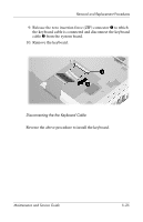
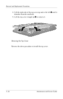
assembly to the notebook., Reverse the above procedure to install the display assembly.
 |
View all HP Nx9600 manuals
Add to My Manuals
Save this manual to your list of manuals |
Page 109 highlights
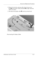
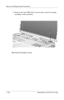
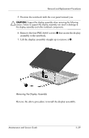
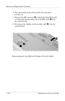
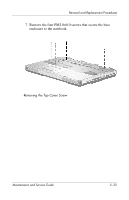
Removal and Replacement Procedures 5. Position the notebook with the rear panel toward you. Ä CAUTION: Support the display assembly when removing the following screws. Failure to support the display assembly can result in damage to the display assembly and other notebook components. 6. Remove the four PM2.0×8.0 screws 1 that secure the display assembly to the notebook. 7. Lift the display assembly straight up to remove it 2. Removing the Display Assembly Reverse the above procedure to install the display assembly. Maintenance and Service Guide 5-29
-
 1
1 -
2
-
3
-
4
-
5
-
6
-
7
-
8
-
9
-
10
-
11
-
12
-
13
-
14
-
15
-
16
-
17
-
18
-
19
-
20
-
21
-
22
-
23
-
24
-
25
-
26
-
27
-
28
-
29
-
30
-
31
-
32
-
33
-
34
-
35
-
36
-
37
-
38
-
39
-
40
-
41
-
42
-
43
-
44
-
45
-
46
-
47
-
48
-
49
-
50
-
51
-
52
-
53
-
54
-
55
-
56
-
57
-
58
-
59
-
60
-
61
-
62
-
63
-
64
-
65
-
66
-
67
-
68
-
69
-
70
-
71
-
72
-
73
-
74
-
75
-
76
-
77
-
78
-
79
-
80
-
81
-
82
-
83
-
84
-
85
-
86
-
87
-
88
-
89
-
90
-
91
-
92
-
93
-
94
-
95
-
96
-
97
-
98
-
99
-
100
-
101
-
102
-
103
-
 104
104 -
 105
105 -
 106
106 -
 107
107 -
 108
108 -
 109
109 -
 110
110 -
 111
111 -
 112
112 -
 113
113 -
 114
114 -
115
-
116
-
117
-
118
-
119
-
120
-
121
-
122
-
123
-
124
-
125
-
126
-
127
-
128
-
129
-
130
-
131
-
132
-
133
-
134
-
135
-
136
-
137
-
138
-
139
-
140
-
141
-
142
-
143
-
144
-
145
-
146
-
147
-
148
-
149
-
150
-
151
-
152
-
153
-
154
-
155
-
156
-
157
-
158
-
159
-
160
-
161
-
162
-
163
-
164
-
165
-
166
-
167
-
168
-
169
-
170
-
171
-
172
-
173
-
174
-
175
-
176
-
177
-
178
-
179
-
180
-
181
-
182
-
183
-
184
-
185
-
186
-
187
-
188
-
189
-
190
-
191
-
192
-
193
-
194
-
195
-
196
-
197
-
198
 |
 |

Removal and Replacement Procedures
Maintenance and Service Guide
5–29
5. Position the notebook with the rear panel toward you.
Ä
CAUTION:
Support the display assembly when removing the following
screws. Failure to support the display assembly can result in damage to
the display assembly and other notebook components.
6.
Remove the four PM2.0×8.0 screws
1
that secure the display
assembly to the notebook.
7. Lift the display assembly straight up to remove it
2
.
Removing the Display Assembly
Reverse the above procedure to install the display assembly.