HP P6000 HP P6300/P6500 EVA iSCSI or iSCSI/FCoE Controller Enclosure Replaceme - Page 2
Saving the iSCSI or iSCSI/FCoE module's, persistent data, Verifying component failure - specification
 |
View all HP P6000 manuals
Add to My Manuals
Save this manual to your list of manuals |
Page 2 highlights
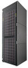
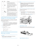
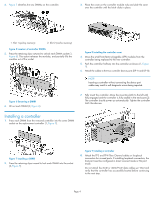
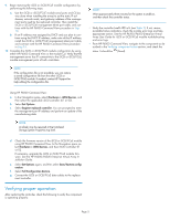
• Ensure that the backup configuration settings and correct firmware version of the iSCSI or iSCSI/FCoE module are available to restore or install in a replacement controller. Attempt to save a backup of your iSCSI or iSCSI/FCoE module configuration file, as noted in this document, if you have not previously done so. • Alloy (gray)-colored latches on components like the controller means the component is warm-swappable. Halt the I/O of the failing controller with HP P6000 Command View before removing this component. See "Halting I/O on the failing controller" on page 3. • There are two controllers at the rear of the controller enclosure. See Figure 1 for the locations. 1. Controller 1 Figure 1 Controller locations . 2. Controller 2 Saving the iSCSI or iSCSI/FCoE module's persistent data NOTE: HP recommends that you save the iSCSI or iSCSI/FCoE module's persistent data periodically to avoid data loss from hardware or software errors. Be sure to save the configuration information from each iSCSI or iSCSI/FCoE module before you replace either controller. Document each of the iSCSI or iSCSI/FCoE telnet management port's static or dynamic (DHCP) IP addresses; they will be needed when configuring the replacement controller. To save the iSCSI or iSCSI/FCoE module configuration, use HP P6000 Command View: 1. In the Navigation pane, select Hardware > iSCSI Devices > iSCSI Controller 01. 2. Select Set Options. 3. Select Save/Restore configuration. 4. Select either Save Configuration or Full Configuration Restore. 5. Save the iSCSIContrConfig0001.tgz file. NOTE: When prompted to save the file, use a unique file name that includes the controller number, and it is suggested the file be saved to a unique array-named folder. 6. In the Navigation pane, select Hardware > iSCSI Devices > iSCSI Controller 02. 7. Repeat steps 2 through 5 for the other iSCSI or iSCSI/FCoE module. Verifying component failure Use the following methods to verify component failure: • Analyze any failure messages received. HP Insight Remote Support provides a recommended fault monitoring solution. • Check status using HP P6000 Command View: 1. In the navigation pane, select Storage system > Hardware > Controller Enclosure and then select a controller. The status is displayed in the Condition/State field. An opera- tional state of (Failed) would indicate a fault that may require a replacement. 2. To check the status of the iSCSI or iSCSI/FCoE module, in the navigation pane, select Storage system > Hardware > iSCSI Devices and then select a controller in the iSCSI Controller Properties window. The states are: not installed, good, attention required, failed, and unknown. 3. To help identify the correct controller, click Locate > Locate On. This causes the blue UID indicator to light on the controller module at the rear of the controller enclosure. • For information about failures or degraded performance with the iSCSI or iSCSI/FCoE module, see the HP P6300/P6500 Enterprise Virtual Array User Guide. To obtain this guide, go to http:// www.hp.com/support/manuals, click Disk Storage Systems in the storage section, and select your model under P6000/EVA Disk Arrays. • Check the controller status LEDs as shown in Figure 2 and Table 1. Figure 2 Controller status LEDs . Table 1 Controller status LEDs Item LED Indication Blue LED identifies a specific controller 1 within the enclosure and the iSCSI or iSC- SI/FCoE module within the controller. Green LED indicates controller health. LED 2 flashes green during boot and becomes solid green after boot. Flashing amber indicates a controller termin- ation, or the system is inoperative and at- tention is required. Solid amber indicates 3 that the controller cannot reboot, and that the controller should be replaced. If both the solid amber and solid blue LEDs are lit, the controller has completed a warm remov- al procedure, and can be safely swapped. Page 2
-
 1
1 -
 2
2 -
 3
3 -
 4
4 -
 5
5
 |
 |