HP P6000 HP P6300/P6500 EVA iSCSI or iSCSI/FCoE Controller Enclosure Replaceme - Page 4
Installing a controller - memory
 |
View all HP P6000 manuals
Add to My Manuals
Save this manual to your list of manuals |
Page 4 highlights
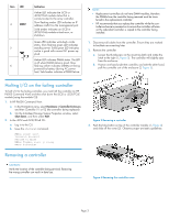
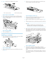
4. Figure 5 identifies the two DIMMs on the controller. 3. Place the cover on the controller module rails and slide the cover over the controller until the latch clicks in place. 1. Slot 1 (policy memory) 2. Slot 2 (cache memory) Figure 5 Location of controller DIMMs . 5. Press the retaining clips outward to unlock each DIMM socket (1, Figure 6). This action releases the modules, and partially lifts the modules out of the socket. Figure 8 Installing the controller cover . 4. Move the small form-factor pluggable (SFP) modules from the controller being replaced to the new controller. 5. Push the controller halfway into the controller enclosure (1, Figure 9). 6. Attach the cables to the two controller device ports (DP-A and DP-B). NOTE: Inserting a controller without connecting the device port cables may result in soft diagnostic errors being reported. Figure 6 Removing a DIMM . 6. Lift out each DIMM (2, Figure 6). 7. Fully insert the controller. Move the mounting latch to the left until fully engaged and the controller is fully seated in the enclosure (2). The controller should power up automatically. Tighten the controller latch thumbscrew. Installing a controller 1. Press each DIMM from the removed controller into the same DIMM socket on the replacement controller (1, Figure 7). Figure 7 Installing a DIMM . 2. Press the retaining clips inward to lock each DIMM into the socket (2, Figure 7). Figure 9 Installing a controller . 8. Attach the FP3 and FP4 Fibre Channel cables or loopback connectors for unused ports. If installing loopback connectors, the host port must be configured in direct connect mode or NL port mode. Do not attach the iSCSI or iSCSI/FCoE data cables yet. Wait and verify that the controller has successfully booted before continuing to the next step. Page 4
-
 1
1 -
 2
2 -
 3
3 -
 4
4 -
 5
5
 |
 |
