HP Pavilion 11-n200 Maintenance and Service Guide
HP Pavilion 11-n200 Manual
 |
View all HP Pavilion 11-n200 manuals
Add to My Manuals
Save this manual to your list of manuals |
HP Pavilion 11-n200 manual content summary:
- HP Pavilion 11-n200 | Maintenance and Service Guide - Page 1
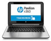
HP Pavilion 11 x360 PC Maintenance and Service Guide IMPORTANT! This document is intended for HP authorized service providers only. - HP Pavilion 11-n200 | Maintenance and Service Guide - Page 2
and services. Nothing herein should be construed as constituting an additional warranty. HP shall not be liable for technical or editorial errors or omissions contained herein. Second Edition: November 2015 First Edition: December 2014 Document Part Number: 798989-002 Product notice This user guide - HP Pavilion 11-n200 | Maintenance and Service Guide - Page 3
Safety warning notice WARNING! To reduce the possibility of heat-related injuries or of overheating the device, do not place the device directly on your lap or obstruct the device air vents. Use the device only on a hard, flat surface. Do not allow another hard surface, such as an adjoining optional - HP Pavilion 11-n200 | Maintenance and Service Guide - Page 4
iv Safety warning notice - HP Pavilion 11-n200 | Maintenance and Service Guide - Page 5
your notebook to an entertainment stand 8 Changing your notebook to a tablet 8 Top ...9 TouchPad ...9 Lights ...10 Keys ...11 Service tag and PCID label ...12 Service tag ...12 PCID label ...13 3 Illustrated parts catalog ...14 Computer major components ...14 Mass storage devices ...17 Display - HP Pavilion 11-n200 | Maintenance and Service Guide - Page 6
Bottom cover ...26 USB/audio board ...29 WLAN module ...30 WWAN module ...32 Solid-state drive (M.2) ...34 Hard drive ...35 RTC battery ...38 Memory module ...40 Power button board ...42 Fan ...44 Heat sink ...46 Battery ...48 Speakers ...49 TouchPad button board ...50 Display assembly ...52 Power - HP Pavilion 11-n200 | Maintenance and Service Guide - Page 7
Restore and recovery ...74 Recovering using HP Recovery Manager 74 What you need to know before you get started 74 Using the HP Recovery partition (select products only 75 Using HP Recovery media to recover 75 Changing the computer boot order 76 Removing the HP Recovery partition (select - HP Pavilion 11-n200 | Maintenance and Service Guide - Page 8
viii - HP Pavilion 11-n200 | Maintenance and Service Guide - Page 9
Celeron N2820 processor (2.13 GHz/2.39 GHz, 1 MB L2, 1066 MHz), dual core Intel Bay Trail-M SoC Internal graphics: Intel HD Graphics Support for DX11 Support for HD playback, streaming, and recording @ 720p 30fps 11.6-in [29.5-cm] (1366×768), high-definition (HD), white light emitting diode (WLED - HP Pavilion 11-n200 | Maintenance and Service Guide - Page 10
: HD (1280×720 by 30 frames per second), fixed (no tilt), with activity light Realtek ALC3227-CG audio codec Two speakers Beats Audio Dual Speakers support 25 mm x 14 mm speaker Formats: MP3, AAC,AAC+, EAAC+ OGG, MIDI Ethernet Integrated 10/100 network interface card (NIC) Co-layout with Giga-LAN - HP Pavilion 11-n200 | Maintenance and Service Guide - Page 11
battery: ● Embedded 2-cell, 29-Wh, Li-ion battery Supports battery fast charge Security Kensington Lock slot TPM (Trusted Platform Module ) Operating system Preinstalled: Windows 10 Windows 8.1 Windows 8.1 Small Screen Touch Serviceability End user replaceable parts: AC adapter WWAN SIM card - HP Pavilion 11-n200 | Maintenance and Service Guide - Page 12
only) Description ● Blinking white: The hard drive is being accessed. ● Amber: HP 3D DriveGuard has temporarily parked the hard drive. Supports a wireless subscriber identity module (SIM). (3) Memory card reader (4) USB 2.0 port (5) USB 3.0 port Reads optional memory cards that enable you to - HP Pavilion 11-n200 | Maintenance and Service Guide - Page 13
Left side Component (1) (2) (3) (4) (5) (6) Description Security cable slot Attaches an optional security cable to the computer. NOTE: The security cable is designed to act as a deterrent, but it may not prevent the computer from being mishandled or stolen. Power button ● When the computer is - HP Pavilion 11-n200 | Maintenance and Service Guide - Page 14
a device is connected to the jack, the computer speakers are disabled. NOTE: Be sure that the device cable has a 4-conductor connector that supports both audio-out (headphone) and audioin (microphone). Controls speaker volume. To decrease speaker volume, press the - edge of the button. To increase - HP Pavilion 11-n200 | Maintenance and Service Guide - Page 15
the section of the Regulatory, Safety, and Environmental Notices that applies to your country or region. To access this document: From the Start screen, type support, and then select the HP - HP Pavilion 11-n200 | Maintenance and Service Guide - Page 16
Your computer can function as a classic notebook, and in addition, the display can be rotated so that the computer transforms into an entertainment stand or a tablet. Changing your notebook to an entertainment stand To change your notebook to an entertainment stand, raise the display, and then - HP Pavilion 11-n200 | Maintenance and Service Guide - Page 17
button (3) Right TouchPad button Description Reads your finger gestures to move the pointer or activate items on the screen. NOTE: The TouchPad also supports edge-swipe gestures. Functions like the left button on an external mouse. Functions like the right button on an external mouse. Top 9 - HP Pavilion 11-n200 | Maintenance and Service Guide - Page 18
Lights Component (1) (2) Caps lock light Mute light Description On: Caps lock is on, which switches the keys to all capital letters. ● Amber: Computer sound is off. ● Off: Computer sound is on. 10 Chapter 2 External component identification - HP Pavilion 11-n200 | Maintenance and Service Guide - Page 19
Keys Component (1) (2) esc key fn key (3) Windows key (4) Action keys Description Displays system information when pressed in combination with the fn key. Executes frequently used system functions when pressed in combination with the esc key, or on select models, the b key or the spacebar. - HP Pavilion 11-n200 | Maintenance and Service Guide - Page 20
about the product's hardware components. The part number helps a service technician to determine what components and parts are needed. ● Model Model is the alphanumeric identifier used to locate documents, drivers, and support for the computer. Warranty describes the duration (in years) of the - HP Pavilion 11-n200 | Maintenance and Service Guide - Page 21
replacing the system board. The label may have a different number of characters depending on the operating system on the computer. Windows 8 models Non-Windows 8 models Service tag and PCID label 13 - HP Pavilion 11-n200 | Maintenance and Service Guide - Page 22
major components NOTE: HP continually improves and changes product parts. For complete and current information on supported parts for your computer, go to http://partsurfer.hp.com, select your country or region, and then follow the on-screen instructions. 14 Chapter 3 Illustrated parts catalog - HP Pavilion 11-n200 | Maintenance and Service Guide - Page 23
Item Component Spare part number (1) Display assembly (11.6-in [29.5-cm], AG, SVA, LED TouchScreen) (includes webcam/microphone module) For use in model numbers Pavilion 11-n000 x360 ~ Pavilion 11-n099 x360 without WWAN 755730-001 For use in model numbers Pavilion 11-n000 x360 ~ Pavilion 11- - HP Pavilion 11-n200 | Maintenance and Service Guide - Page 24
Item (7) (8) (9) (10) (11) (12) (13) (14) Component Spare part number Intel Celeron N2830 processor and the Windows 10 operating system for use in models without WWAN 764235-601 Intel Celeron N2830 processor and the Windows 8.1 Standard operating system for use in models without WWAN 764235- - HP Pavilion 11-n200 | Maintenance and Service Guide - Page 25
Item Component Spare part number Broadcom BCM43142 802.11 bgn 1x1 Wi-Fi + BT4.0 HMC Combo Adapter with 1 antenna 753076-005 Intel Dual Band Wireless-AC 3160 802.11 ac 1x1 WiFi + BT 4.0 Combo Adapter with 2 antenna 784638-005 Intel Dual Band Wireless-AC 3160 802.11a/b/g/n/ac (1x1) WiFi and - HP Pavilion 11-n200 | Maintenance and Service Guide - Page 26
Display assembly subcomponents Item (1) (2) (3) (4) Component Display enclosure Silver models with WWAN Silver models without WWAN Red models with WWAN Red models without WWAN Purple models without WWAN Purple models with WWAN Display cable Webcam Display hinge covers For use in red models For use - HP Pavilion 11-n200 | Maintenance and Service Guide - Page 27
Item Component Spare part number WLAN antenna for use on models with all WLAN modules except for Intel Dual Band Wireless-AC 3160 802.11 ac 1x1 WiFi + BT 4.0 Combo Adapter 805106-001 WLAN antenna for use on models with the following WLAN module: Intel Dual Band Wireless- 805725-001 AC 3160 802. - HP Pavilion 11-n200 | Maintenance and Service Guide - Page 28
screw driver ● Magnetic screw driver ● Phillips P0 and P1 screw drivers Service considerations The following sections include some of the considerations that you must keep the points designated in the maintenance instructions. 20 Chapter 4 Removal and replacement procedures preliminary requirements - HP Pavilion 11-n200 | Maintenance and Service Guide - Page 29
Cables and connectors CAUTION: When servicing the computer, be sure that cables are placed in their proper locations during the reassembly process. Improper the drive in a bubble pack mailer or other suitable form of protective packaging and label the package "FRAGILE." Service considerations 21 - HP Pavilion 11-n200 | Maintenance and Service Guide - Page 30
Grounding guidelines Electrostatic discharge damage Electronic components are sensitive to electrostatic discharge (ESD). Circuitry design and structure determine the degree of sensitivity. Networks built into many integrated circuits provide some protection, but in many cases, ESD contains enough - HP Pavilion 11-n200 | Maintenance and Service Guide - Page 31
material. ● Use a wrist strap connected to a properly grounded work surface and use properly grounded tools and equipment. ● Use conductive field service tools, such as cutters, screw drivers, and vacuums. ● When fixtures must directly contact dissipative surfaces, use fixtures made only of static - HP Pavilion 11-n200 | Maintenance and Service Guide - Page 32
with ground cords of one megohm resistance ● Static-dissipative tables or floor mats with hard ties to the ground ● Field service kits ● Static awareness labels ● Material-handling packages ● Nonconductive plastic bags, tubes, or boxes ● Metal tote boxes ● Electrostatic voltage levels and - HP Pavilion 11-n200 | Maintenance and Service Guide - Page 33
current information on supported parts for your computer, go to http://partsurfer.hp.com, select your country or region, and then follow the on-screen instructions. Component replacement procedures This chapter provides removal and replacement procedures for Authorized Service Provider only parts - HP Pavilion 11-n200 | Maintenance and Service Guide - Page 34
bottom cover: 1. Position the computer upside-down. 2. Pry the two rear rubber feet off the bottom cover (1). 26 Chapter 5 Removal and replacement procedures for Authorized Service Provider parts - HP Pavilion 11-n200 | Maintenance and Service Guide - Page 35
3. Remove the two Phillips PM2.5×8.0 screws (2) that secure the bottom cover to the computer. 4. Remove the two Phillips PM2.5×8.0 screws (1) and the seven Phillips PM2.0×7.0 screws (2) that secure the bottom cover to the computer. Component replacement procedures 27 - HP Pavilion 11-n200 | Maintenance and Service Guide - Page 36
USB/audio board cable from the system board connector (2). Reverse this procedure to install the bottom cover. 28 Chapter 5 Removal and replacement procedures for Authorized Service Provider parts - HP Pavilion 11-n200 | Maintenance and Service Guide - Page 37
USB/audio board Description USB/audio board (includes cable) Spare part number 755734-001 Before removing the USB/audio board, follow these steps: 1. Shut down the computer. If you are unsure whether the computer is off or in Hibernation, turn the computer on, and then shut it down through the - HP Pavilion 11-n200 | Maintenance and Service Guide - Page 38
then receive a warning message, remove the module to restore device functionality, and then contact technical support. Before removing the WLAN module, follow these steps: 1. Turn off the computer. If you up.) 30 Chapter 5 Removal and replacement procedures for Authorized Service Provider parts - HP Pavilion 11-n200 | Maintenance and Service Guide - Page 39
3. Remove the WLAN module (3) by pulling the module away from the slot at an angle. NOTE: If the WLAN antenna cables are not connected to the terminals on the WLAN module, the protective sleeves must be installed on the antenna connectors, as shown in the following illustration. Reverse this - HP Pavilion 11-n200 | Maintenance and Service Guide - Page 40
module "Aux" terminal. 2. Remove the Phillips PM2.0×3.0 screw (2) that secures the WWAN module to the system board. 32 Chapter 5 Removal and replacement procedures for Authorized Service Provider parts - HP Pavilion 11-n200 | Maintenance and Service Guide - Page 41
3. Remove the WWAN module (3) by pulling the module away from the slot. NOTE: WWAN modules are designed with a notch to prevent incorrect insertion. NOTE: If the WWAN antennas are not connected to the terminals on the WWAN module, the protective sleeves must be installed on the antenna connectors, - HP Pavilion 11-n200 | Maintenance and Service Guide - Page 42
drive away from the slot at an angle. Reverse this procedure to install the solid-state drive. 34 Chapter 5 Removal and replacement procedures for Authorized Service Provider parts - HP Pavilion 11-n200 | Maintenance and Service Guide - Page 43
Hard drive NOTE: The Hard Drive Hardware Kit, spare part number 755740-001, includes the hard drive bracket, hard drive connector cable, and screws. The Solid-State Drive Hardware Kit, spare part number 783845-001 includes the connector cable, top and bottom brackets, PCBA, and screws. Description - HP Pavilion 11-n200 | Maintenance and Service Guide - Page 44
connector cable, and screws are available in the Hard Drive Hardware Kit, spare part number 755740-001. 36 Chapter 5 Removal and replacement procedures for Authorized Service Provider parts - HP Pavilion 11-n200 | Maintenance and Service Guide - Page 45
Reverse this procedure to install the hard drive. Component replacement procedures 37 - HP Pavilion 11-n200 | Maintenance and Service Guide - Page 46
26). 5. Disconnect the battery. Remove the RTC battery: 1. Disconnect the RTC battery cable (1) from the system board. 38 Chapter 5 Removal and replacement procedures for Authorized Service Provider parts - HP Pavilion 11-n200 | Maintenance and Service Guide - Page 47
2. Detach the RTC battery (2) from the system board. (The RTC battery is secured with double-sided tape.) 3. Remove the RTC battery. Reverse this procedure to install the RTC battery. Component replacement procedures 39 - HP Pavilion 11-n200 | Maintenance and Service Guide - Page 48
memory may result in various system problems. To update BIOS: 1. Navigate to www.hp.com. 2. Click Support & Drivers > click Drivers & BIOS. 8. Click the Download button, and then follow the on-screen instructions. Before removing a memory module, follow these steps: 1. Turn off Service Provider parts - HP Pavilion 11-n200 | Maintenance and Service Guide - Page 49
1. Spread the retaining tabs (1) on each side of the memory module slot to release the memory module. (The memory module tilts up.) 2. Remove the memory module (2) by pulling the module away from the slot at an angle. Reverse this procedure to install a memory module. Component replacement - HP Pavilion 11-n200 | Maintenance and Service Guide - Page 50
system board. 2. Remove the two Phillips PM2.0×3.0 screws (2) that secure the power button board to the computer. 42 Chapter 5 Removal and replacement procedures for Authorized Service Provider parts - HP Pavilion 11-n200 | Maintenance and Service Guide - Page 51
3. Remove the power button board and cable (3). Reverse this procedure to install the power button board. Component replacement procedures 43 - HP Pavilion 11-n200 | Maintenance and Service Guide - Page 52
tape (3) from the heat sink. NOTE: You do not need to remove the tape from the fan. 44 Chapter 5 Removal and replacement procedures for Authorized Service Provider parts - HP Pavilion 11-n200 | Maintenance and Service Guide - Page 53
4. Remove the fan (4). Reverse this procedure to install the fan. Component replacement procedures 45 - HP Pavilion 11-n200 | Maintenance and Service Guide - Page 54
heat sink, remove the four Phillips PM2.0×3.0 screws (1) that secure the heat sink to the system board. 46 Chapter 5 Removal and replacement procedures for Authorized Service Provider parts - HP Pavilion 11-n200 | Maintenance and Service Guide - Page 55
and the system board components each time the heat sink is removed. Thermal paste is used on the processor (1) and the heat sink section (2) that services it Reverse this procedure to install the heat sink. Component replacement procedures 47 - HP Pavilion 11-n200 | Maintenance and Service Guide - Page 56
(2) that secure the battery to the computer. 3. Remove the battery (3). Reverse this procedure to install the battery. 48 Chapter 5 Removal and replacement procedures for Authorized Service Provider parts - HP Pavilion 11-n200 | Maintenance and Service Guide - Page 57
Speakers Description Speaker Kit (includes left and right speakers and cable) Spare part number 755738-001 Before removing the speakers, follow these steps: 1. Turn off the computer. If you are unsure whether the computer is off or in Hibernation, turn the computer on, and then shut it down - HP Pavilion 11-n200 | Maintenance and Service Guide - Page 58
the computer. 4. Lift the foil and rubber gaskets from atop the left and right broadhead screw holes (1). 50 Chapter 5 Removal and replacement procedures for Authorized Service Provider parts - HP Pavilion 11-n200 | Maintenance and Service Guide - Page 59
5. Lift the bottom of the touchpad upward (2), and then lift it off the computer (3). Reverse this procedure to install the TouchPad button board. Component replacement procedures 51 - HP Pavilion 11-n200 | Maintenance and Service Guide - Page 60
enclosure. NOTE: The number of antenna cables may vary. 2. Disconnect the webcam cable (2) from the system board. 52 Chapter 5 Removal and replacement procedures for Authorized Service Provider parts - HP Pavilion 11-n200 | Maintenance and Service Guide - Page 61
the two black Phillips PM2.5×5.0 screws (3) that secure the display assembly and bracket to the computer. CAUTION: Support the display assembly when removing the screws. Failure to support the display assembly can result in damage to the display assembly and other computer components. 6. Lift the - HP Pavilion 11-n200 | Maintenance and Service Guide - Page 62
the two screw covers (1). b. Remove the two Phillips PM2.5×4.0 screws (2) that secure the enclosure to the display. 54 Chapter 5 Removal and replacement procedures for Authorized Service Provider parts - HP Pavilion 11-n200 | Maintenance and Service Guide - Page 63
c. Pry from the side to separate the enclosure from the display (3). 2. To remove the webcam module: NOTE: The webcam is available using spare part number 758848-001. a. Lift the webcam module (1) enough to gain access to the cable. b. Disconnect the cable (2) from the module. 3. To remove the - HP Pavilion 11-n200 | Maintenance and Service Guide - Page 64
display panel (1). b. Disconnect the display cable from the large connector on the bottom of the display panel (2). 56 Chapter 5 Removal and replacement procedures for Authorized Service Provider parts - HP Pavilion 11-n200 | Maintenance and Service Guide - Page 65
c. Remove the cable from the tape (3) and clips (4) that secure it to the display enclosure , and then lift the display cable from the display enclosure (5). 5. To remove the sensor board: NOTE: The sensor board is available using spare part number 788218-001. a. Disconnect the cable from the board - HP Pavilion 11-n200 | Maintenance and Service Guide - Page 66
(6) from the computer. 6. Remove the power connector cable. Reverse this procedure to install the power connector cable. 58 Chapter 5 Removal and replacement procedures for Authorized Service Provider parts - HP Pavilion 11-n200 | Maintenance and Service Guide - Page 67
System board NOTE: The system board spare part kit includes replacement thermal material. Description System board for use in models equipped with: Intel Pentium N3540 processor and the Windows 8.1 Standard operating system Intel Pentium N3540 processor and a non-Windows 8 operating system Intel - HP Pavilion 11-n200 | Maintenance and Service Guide - Page 68
): Hard drive cable 2. Remove the four Phillips PM2.0×3.0 screws (1) that secure the system board to the computer. 60 Chapter 5 Removal and replacement procedures for Authorized Service Provider parts - HP Pavilion 11-n200 | Maintenance and Service Guide - Page 69
3. Remove the system board (2) from the computer. Reverse this procedure to install the system board. Component replacement procedures 61 - HP Pavilion 11-n200 | Maintenance and Service Guide - Page 70
the hard drive (see Hard drive on page 35). 6. Remove the fan (see Fan on page 44). 62 Chapter 5 Removal and replacement procedures for Authorized Service Provider parts - HP Pavilion 11-n200 | Maintenance and Service Guide - Page 71
7. Remove the heat sink (see Heat sink on page 46). 8. Remove the battery (see Battery on page 48). 9. Remove the system board (see System board on page 59). Remove the keyboard: 1. Remove the 16 Phillips PM2.0×3.0 screws that secure the keyboard to the top cover. 2. Remove the keyboard from the - HP Pavilion 11-n200 | Maintenance and Service Guide - Page 72
named Readme.txt, which contains information regarding installing and troubleshooting the file. Determining the BIOS version To decide whether also known as ROM date and System BIOS): 1. Type support in the taskbar search box, and then select the HP Support Assistant app. - or - 64 Chapter 6 Using - HP Pavilion 11-n200 | Maintenance and Service Guide - Page 73
in the taskbar search box, and then select the HP Support Assistant app. - or - Click the question mark icon in the taskbar. 2. Click Updates, and then click Check for updates and messages. 3. Follow the on-screen instructions. 4. At the download area, follow these steps: a. Identify the most - HP Pavilion 11-n200 | Maintenance and Service Guide - Page 74
that has an .exe extension (for example, filename.exe). The BIOS installation begins. 5. Complete the installation by following the on-screen instructions. NOTE: After a message on the screen reports a successful installation, you can delete the downloaded file from your hard drive. Synchronizing - HP Pavilion 11-n200 | Maintenance and Service Guide - Page 75
which contains information regarding installing and troubleshooting the file. Determining the BIOS version can be revealed from the Start screen by typing support, selecting the HP Support Assistant app, and then selecting System Information, or screen instructions. Starting Setup Utility (BIOS) 67 - HP Pavilion 11-n200 | Maintenance and Service Guide - Page 76
and then select the HP Support Assistant app. ‒ or - From the Windows desktop, click the question mark icon in the notification area, at the far right of the taskbar. 2. Click Updates and tune-ups, and then click Check for HP updates now. 3. Follow the on-screen instructions. 4. At the download area - HP Pavilion 11-n200 | Maintenance and Service Guide - Page 77
Synchronizing a tablet and keyboard (select models only) When you attach a tablet to the keyboard and restart the computer, the BIOS checks to see if the Embedded Controller firmware on the keyboard needs to be synchronized. If so, BIOS will start the synchronization. If the synchronization is - HP Pavilion 11-n200 | Maintenance and Service Guide - Page 78
71. b. Hard drive c. BIOS 3. When the diagnostic tool opens, select the type of diagnostic test you want to run, and then follow the on-screen instructions. On a tablet, press the volume down button to stop a diagnostic test. NOTE: If you need to stop a diagnostic test on computers or tablets with - HP Pavilion 11-n200 | Maintenance and Service Guide - Page 79
for a specific product: 1. Go to http://www.hp.com/support, and then select your country. The HP Support page is displayed. 2. Click Drivers & Downloads. 3. In the system. 5. In the Diagnostic section, follow the on-screen instructions to select and download the UEFI version you want. Downloading HP - HP Pavilion 11-n200 | Maintenance and Service Guide - Page 80
the Recovery partition, you can obtain recovery media for your system from support. See the Worldwide Telephone Numbers booklet included with the computer. You can Go to http://www.hp.com/support, select your country or region, and follow the on-screen instructions. 72 Chapter 9 Backing up, restoring - HP Pavilion 11-n200 | Maintenance and Service Guide - Page 81
with the computer. You can also find contact information on the HP website. Go to http://www.hp.com/ support, select your country or region, and follow the on-screen instructions. ◦ Be sure that the computer is connected to AC power before you begin creating the recovery media. ◦ The creation - HP Pavilion 11-n200 | Maintenance and Service Guide - Page 82
app. ● If you need to correct a problem with a preinstalled application or driver, use the applications, and then follow the on-screen instructions. ● If you want to recover the you can obtain recovery media for your system from support. See the Worldwide Telephone Numbers booklet included with - HP Pavilion 11-n200 | Maintenance and Service Guide - Page 83
to http://www.hp.com/support, select your country or region, and follow the on-screen instructions. IMPORTANT: HP Recovery Manager then select f11. 2. Select Troubleshoot from the boot options menu. 3. Select Recovery Manager, and then follow the on-screen instructions. Using HP Recovery media to - HP Pavilion 11-n200 | Maintenance and Service Guide - Page 84
drive from which you want to boot. 4. Follow the on-screen instructions. Removing the HP Recovery partition (select products only) HP Recovery Manager The Remove Recovery Partition option is only available on products that support this function. Follow these steps to remove the HP Recovery partition - HP Pavilion 11-n200 | Maintenance and Service Guide - Page 85
with the computer. You can also find contact information from the HP website. Go to http://www.hp.com/support, select your country or region, and follow the on-screen instructions. HP Recovery Manager is a software program that allows you to create recovery media after you successfully set up the - HP Pavilion 11-n200 | Maintenance and Service Guide - Page 86
included with the computer. You can also find contact information from the HP website. Go to http://www.hp.com/support, select your country or region, and follow the on-screen instructions. If you use an external optical drive, it must be connected directly to a USB port on the computer; the drive - HP Pavilion 11-n200 | Maintenance and Service Guide - Page 87
support, and then select the HP Support Assistant app. - or - From the Windows desktop, click the question mark icon in the notification area, at the far right of the taskbar. ● If you need to correct a problem Reinstall, and then follow the on-screen instructions. ● On select models, if you want - HP Pavilion 11-n200 | Maintenance and Service Guide - Page 88
does not work, you can obtain recovery media for your system from support. See the Worldwide Telephone Numbers booklet included with the computer. You button. 2. Select Troubleshoot from the boot options menu. 3. Select Recovery Manager, and then follow the on-screen instructions. Using HP Recovery - HP Pavilion 11-n200 | Maintenance and Service Guide - Page 89
then tap f9 for boot options. 3. Select the optical drive or USB flash drive from which you want to boot. 4. Follow the on-screen instructions. Removing the HP Recovery partition (select models only) HP Recovery Manager software allows you to remove the HP Recovery partition to free up hard drive - HP Pavilion 11-n200 | Maintenance and Service Guide - Page 90
11 Specifications Computer specifications Metric U.S. Dimensions Width 308 mm 12.13 in Depth 215.1 mm 8.47 in Height 21.9 mm 0.86 in Weight 1.4 kg 3.08 lbs Input power Operating voltage and current 19.5 V dc @ 3.33 A - 65 W Temperature Operating 5°C to 35°C 41°F to 95°F - HP Pavilion 11-n200 | Maintenance and Service Guide - Page 91
°F to 140°F) *1 GB = 1 billion bytes when referring to hard drive storage capacity. Actual accessible capacity is less. NOTE: Certain restrictions and exclusions apply. Contact technical support for details. Hard drive specifications 83 - HP Pavilion 11-n200 | Maintenance and Service Guide - Page 92
12 Power cord set requirements The wide-range input feature of the computer permits it to operate from any line voltage from 100 to 120 volts AC, or from 220 to 240 volts AC. The 3-conductor power cord set included with the computer meets the requirements for use in the country or region where the - HP Pavilion 11-n200 | Maintenance and Service Guide - Page 93
Country/region Accredited agency Applicable note number South Korea EK 4 Sweden CEMKO 1 Switzerland SEV 1 Taiwan BSMI 4 The United Kingdom BSI 1 The United States UL 2 1. The flexible cord must be Type HO5VV-F, 3-conductor, 1.0-mm² conductor size. Power cord set fittings ( - HP Pavilion 11-n200 | Maintenance and Service Guide - Page 94
13 Recycling When a non-rechargeable or rechargeable battery has reached the end of its useful life, do not dispose of the battery in general household waste. Follow the local laws and regulations in your area for battery disposal. HP encourages customers to recycle used electronic hardware, HP - HP Pavilion 11-n200 | Maintenance and Service Guide - Page 95
buttons left TouchPad 9 power 5 right TouchPad 9 C cables, service considerations 21 caps lock light, identifying 10 chipset, product description HP PC Hardware Diagnostics (UEFI) using 70 HP Recovery Manager correcting boot problems 76, 81 starting 75, 80 HP Recovery media creating 72, 77 recovery - HP Pavilion 11-n200 | Maintenance and Service Guide - Page 96
74, 79 P packaging guidelines 23 PCID label 13 plastic parts, service considerations 20 ports HDMI 4 product description 2 USB 2.0 4, 5 USB 73, 75, 78, 80 HP Recovery Manager 74, 79 media 75, 80 starting 75, 80 supported discs 73, 78 system 74, 79 USB flash drive 75, 80 using HP Recovery media 73 - HP Pavilion 11-n200 | Maintenance and Service Guide - Page 97
numbers 34 Speaker Kit, spare part number 16, 49 speakers identifying 6 removal 49 spare part number 16, 49 specifications computer 82 hard drive 83 supported discs, recovery 73, 78 system board removal 59 spare part numbers 15, 59 system recovery 74, 79 system restore point creating 73, 78 system
-
 1
1 -
 2
2 -
 3
3 -
 4
4 -
 5
5 -
 6
6 -
 7
7 -
8
-
9
-
10
-
11
-
12
-
13
-
14
-
15
-
16
-
17
-
18
-
19
-
20
-
21
-
22
-
23
-
24
-
25
-
26
-
27
-
28
-
29
-
30
-
31
-
32
-
33
-
34
-
35
-
36
-
37
-
38
-
39
-
40
-
41
-
42
-
43
-
44
-
45
-
46
-
47
-
48
-
49
-
50
-
51
-
52
-
53
-
54
-
55
-
56
-
57
-
58
-
59
-
60
-
61
-
62
-
63
-
64
-
65
-
66
-
67
-
68
-
69
-
70
-
71
-
72
-
73
-
74
-
75
-
76
-
77
-
78
-
79
-
80
-
81
-
82
-
83
-
84
-
85
-
86
-
87
-
88
-
89
-
90
-
91
-
92
-
93
-
94
-
95
-
96
-
97
 |
 |

HP Pavilion
11
x360 PC
Maintenance and Service Guide
IMPORTANT! This document is intended for HP
authorized service providers only.